 +86-13646196162
 info@hysonindustry.com




 русский
 عربى



U-Head Jack Base: Precision Top Support for Safer and More Accurate Formwork
 2026.10.23
Content
- 1 What Is a U-Head Jack Base?
- 2 Why Top Adjustment Matters in Formwork Construction
- 3 Core Advantages of the U-Head Jack Base
- 4 Comparison with Other Support Components
- 5 Manufacturing Process and Engineering Control
- 6 Advanced Manufacturing Strengths of the Supplier
- 7 Applications in Formwork and Temporary Works
- 8 Installation Recommendations
- 9 Maintenance, Storage, and Service Life
- 10 Customization Options for OEM Projects
- 11 Quality and Safety Considerations
- 12 Why Choose an Integrated Heavy Steel Manufacturer?
- 13 Frequently Asked Questions
- 13.1 What is the main purpose of a U-head jack base?
- 13.2 How is it different from an adjustable base jack?
- 13.3 What adjustment range is available?
- 13.4 What is the adjustment accuracy?
- 13.5 What load can one U-head jack base support?
- 13.6 Which materials are used?
- 13.7 Is the product suitable for ringlock or disc-lock scaffolding?
- 13.8 Can the U-head jack base be used for wall formwork?
- 13.9 Is hot-dip galvanizing available?
- 13.10 Can the dimensions be customized?
- 13.11 Can the component replace system bracing?
- 13.12 How should used components be inspected?
- 13.13 What information should be supplied for an OEM quotation?
- 14 Conclusion
- 15 References
- 16 Product: U-head Jack Base
Modern concrete construction depends on the stability, accuracy, and adjustability of its temporary support systems. Whether a project involves floor slabs, wall panels, bridge structures, precast components, or elevated work platforms, the support arrangement must carry substantial loads while maintaining the required elevation and alignment. Small deviations in support height can affect concrete thickness, slab flatness, wall verticality, connection accuracy, and the final quality of the completed structure.
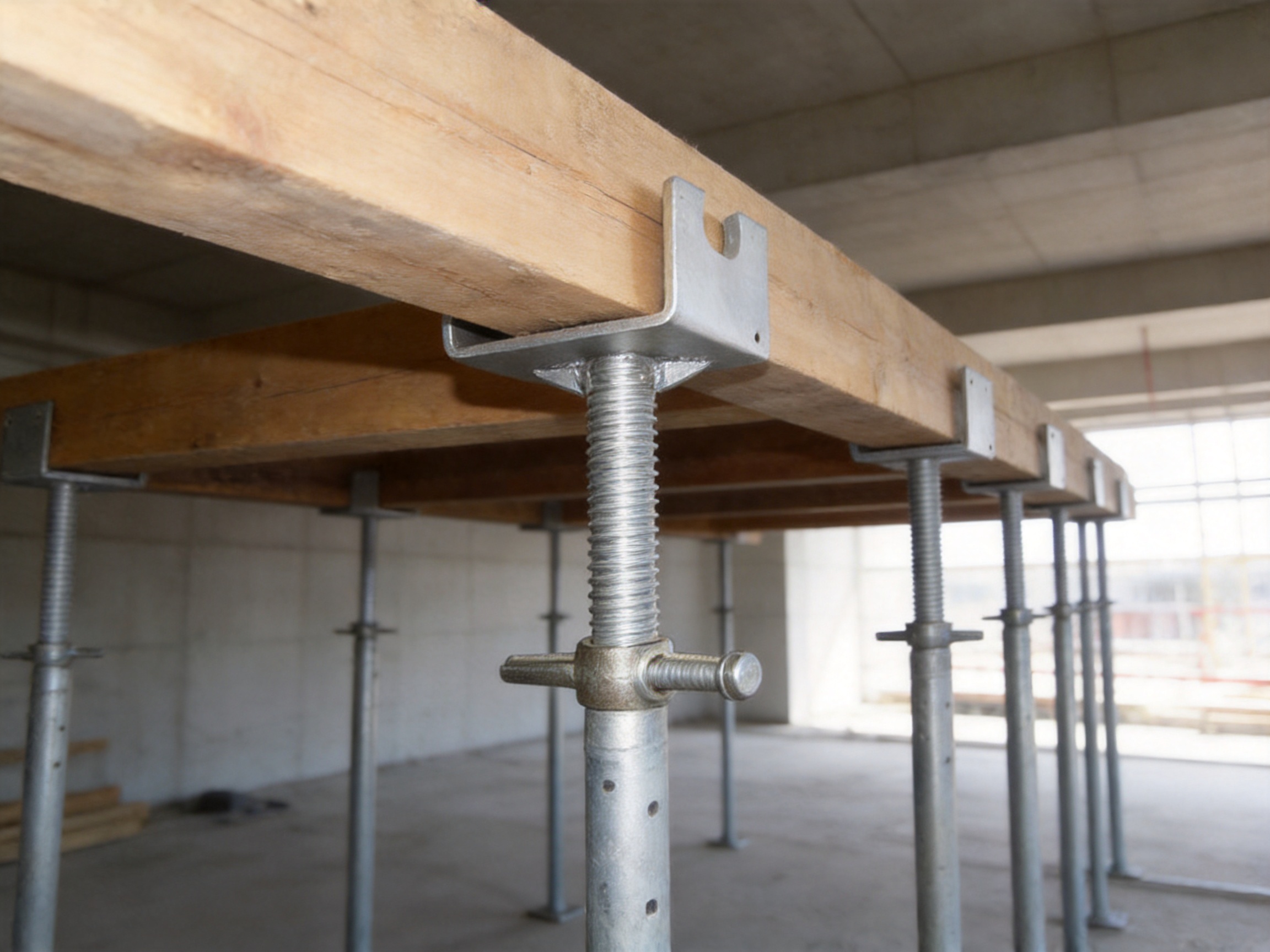
The U-head jack base is designed to address this specific challenge. It is a top-adjustable, load-bearing accessory used at the connection between a support system and the formwork above it. Its U-shaped head securely receives a formwork beam or rib, while its threaded adjustment mechanism enables workers to make accurate height corrections before and during installation. This combination of secure top fitting, controlled fine-tuning, and dependable load transfer makes the U-head jack base an important component in modern formwork and scaffolding systems.
Unlike a standard adjustable base, which is mainly used to level the bottom of a support, the U-head jack base works at the top of the support assembly. Unlike a simple steel prop, it is not limited to providing vertical load-bearing capacity. Its main purpose is to create a stable, adjustable, and well-fitted connection with the formwork. This makes it especially valuable where both structural support and dimensional accuracy are required.
Nantong Hyson Road And Bridge Formwork Co., Ltd. manufactures U-head jack bases together with steel formwork, scaffolding components, steel props, heavy steel structures, and custom fabricated metal products. The company combines precision processing, high-strength steel manufacturing, welding control, surface treatment, and project-based quality management to supply reliable components for demanding construction environments.
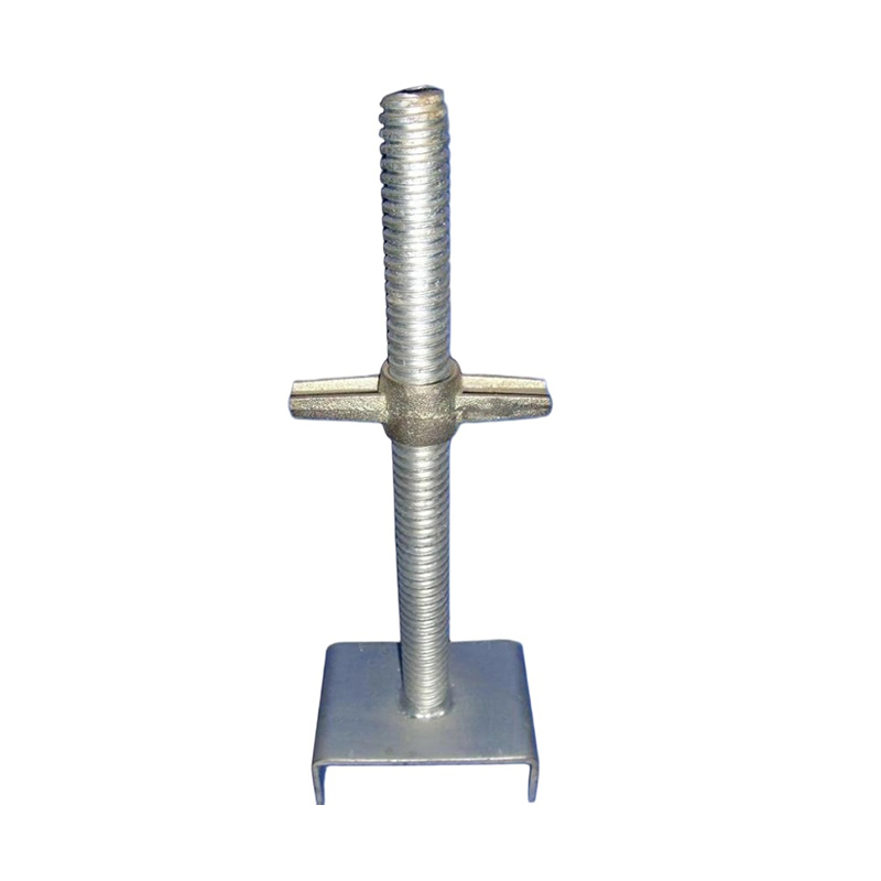
U-head Jack Base
What Is a U-Head Jack Base?
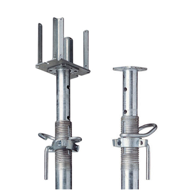
A U-head jack base is a height-adjustable formwork support accessory with a U-shaped top seat. It is installed at the upper end of a support element, such as a steel prop, ringlock or disc-lock scaffolding standard, or another compatible vertical support. The U-shaped head receives the main beam, timber beam, steel beam, or supporting rib of the formwork system.
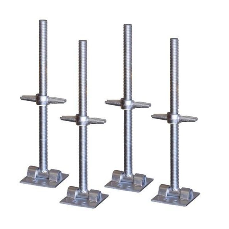
The component normally consists of several key parts: a U-shaped head, a vertical threaded stem, an adjustment nut or collar, and a rotating handle or operating mechanism. Depending on the required configuration, the base may also include a connecting plate, locking feature, or interface designed for use with a specific support system.
During installation, the support structure is placed beneath the formwork. The U-head is positioned directly under the main beam or rib. Workers then rotate the adjustment mechanism to raise or lower the head until the formwork reaches the required elevation. Once the correct height is achieved, the support assembly is checked for stability, alignment, and load distribution.
The U-shaped top is a critical design feature. It provides a larger and more controlled contact area than a flat support plate. The groove helps keep the formwork beam in position and reduces the possibility of lateral movement, sliding, or accidental displacement. At the same time, the threaded adjustment system allows the support height to be corrected without dismantling the entire support arrangement.
In practical construction, the U-head jack base acts as the final adjustment and connection point between the vertical support system and the formwork. This position makes it highly influential in the overall precision of the installation.
Why Top Adjustment Matters in Formwork Construction
Formwork systems are rarely installed on perfectly level surfaces. Variations may occur in the ground, base plates, support lengths, beam dimensions, slab elevations, or assembled components. Even when every individual part is manufactured accurately, accumulated tolerances can create differences in the final formwork level.
Without a top-adjustable component, workers may need to insert packing materials, reposition supports, replace components, or repeatedly dismantle sections of the structure. These methods consume time and can produce uneven load transfer. They may also create unstable contact points that are difficult to inspect and maintain.
A U-head jack base provides a more controlled alternative. Its threaded adjustment mechanism allows the final height to be corrected at the point where the support meets the formwork. The specified adjustment range of 30 mm to 150 mm supports practical leveling and positioning requirements across a variety of applications. The stated adjustment accuracy can reach approximately plus or minus 0.5 mm under suitable operating conditions and proper installation.
Fine adjustment is particularly important for floor slabs. If the formwork is not level, the finished slab may have inconsistent thickness or an uneven surface. In wall formwork, inaccurate support height can contribute to poor verticality, misalignment between panels, or localized pressure on the formwork. In precast installation, accurate temporary support helps workers maintain the required position while permanent connections are completed.
Top adjustment also improves working efficiency. Workers can make corrections from the accessible upper or side operating position instead of modifying the entire lower support arrangement. This can reduce installation time and help construction teams respond more quickly to site tolerances.
Core Advantages of the U-Head Jack Base
U-Shaped Beam Support
The integrated U-shaped groove is designed to receive and hold a formwork beam or rib. Compared with a flat plate, the groove creates a more defined seating position. It helps limit horizontal displacement and gives workers a visible reference for correct beam placement.
The U-shaped support also increases the effective contact area between the jack and the formwork. A larger contact area can reduce concentrated pressure and help distribute loads more evenly. This is important when supporting timber beams, steel beams, aluminum formwork components, or other members with defined dimensions.
A properly fitted U-head can reduce the likelihood of beam rolling, sliding, or shifting during installation and concrete placement. It does not replace the need for bracing, tying, or complete system stabilization, but it contributes to a more secure connection within the support assembly.
Precise Threaded Adjustment
The threaded stem and adjustment nut provide a mechanical method for raising or lowering the formwork. Compared with improvised packing or loose wedges, a threaded adjustment system offers better control and repeatability.
The adjustment mechanism is intended for fine positioning rather than uncontrolled lifting. Workers can rotate the handle or nut incrementally and observe the effect on the formwork elevation. This allows the support system to be brought into alignment with level marks, survey points, or project drawings.
When used correctly, the adjustment range of 30 mm to 150 mm accommodates common height variations in formwork support applications. The fine-thread configuration supports gradual corrections and helps avoid sudden movement. After adjustment, the assembly should be checked and secured according to the project’s installation procedure.
High Load-Bearing Capacity
The U-head jack base is manufactured from high-strength carbon steel grades such as Q235 or Q345, depending on the required configuration and project specification. The U-shaped support is formed through stamping, forging, or other controlled forming processes selected for the component design.
The stated single-support load capacity is approximately 80 kN to 120 kN, subject to the product configuration, effective extension, support condition, load direction, connection system, and applicable engineering requirements. The actual permissible working load must always be verified against technical documentation and the complete formwork design.
High load capacity is not determined by material grade alone. It also depends on the thread quality, stem diameter, head thickness, welding or forming quality, bearing surface, extension length, verticality, and the stability of the entire support system. For this reason, a professionally manufactured U-head jack base should be evaluated as part of a complete engineered assembly rather than as an isolated steel component.
Stable Load Distribution
Concrete and formwork loads are transferred through a chain of components. If one connection point is too small, uneven, or poorly aligned, localized stress may develop. The U-head helps provide a defined bearing seat for the formwork beam, allowing loads to be transferred more evenly into the vertical support.
More uniform load transfer can reduce pressure concentration on timber or steel members. It can also help limit deformation at the connection point. This is especially useful in wide slab formwork, high-load support towers, and applications where multiple beams meet or overlap above the support line.
Load distribution must still be confirmed through structural calculation. The U-head jack base improves the connection condition, but it does not compensate for insufficient bracing, excessive eccentricity, inadequate foundation support, or incorrect spacing between supports.
Compatibility with Different Support Systems
The U-head jack base can be configured for use with steel supports, adjustable bases, disc-lock or ringlock scaffolding standards, coupler-type scaffolding, and other standardized support arrangements. Its value is increased when the interface dimensions are coordinated with existing project equipment.
A standardized connection concept helps contractors integrate the component without extensive modification. It may be used at the top of a vertical prop, support tower, or scaffold standard, depending on the approved application. Compatibility should be checked by confirming thread size, stem diameter, head width, bearing dimensions, and connection details.
For contractors operating several types of temporary works equipment, compatible U-head jack bases can simplify inventory management. The same basic component may support different formwork arrangements, provided that the loading, dimensions, and system approvals are appropriate.
Corrosion Resistance for Construction Environments
Construction sites often expose steel components to rain, humidity, wet concrete, dust, mud, and repeated handling. Corrosion can reduce appearance, affect thread operation, and eventually compromise service life if it is not controlled.
The U-head jack base is available with a hot-dip galvanized surface. The stated coating thickness is at least 75 micrometers for the applicable configuration. Hot-dip galvanizing creates a metallurgically bonded zinc coating that provides a protective barrier and sacrificial corrosion resistance.
Galvanized surfaces are particularly useful for components that are stored outdoors, transported between projects, or used in humid environments. However, galvanizing does not eliminate the need for maintenance. Threads should be kept clean, impact damage should be inspected, and areas with severe coating damage should be treated according to the site maintenance procedure.
Simple and Efficient Operation
The rotating handle is designed to allow height adjustment without requiring complex tools. This can be useful during formwork erection, leveling, inspection, and stripping preparation.
Simple operation is important because temporary works are often installed under time pressure. A component that can be adjusted quickly and visibly helps workers reduce unnecessary dismantling. It also supports more consistent installation practices between different teams and project areas.
Although operation is straightforward, workers should not use excessive impact force, extension bars, or unauthorized tools to force the mechanism. Threads and adjustment nuts should be kept clean and lubricated when required by the manufacturer’s instructions.
Comparison with Other Support Components
The U-head jack base is not intended to replace every type of adjustable support component. Its advantage comes from combining several functions in one upper connection accessory. Understanding the difference between related products helps engineers and contractors select the correct solution.
| Component | Primary Function | Adjustment Position | Connection with Formwork | Typical Advantage |
|---|---|---|---|---|
| U-head jack base | Top support, height adjustment, and beam seating | At the upper support connection | U-shaped groove holds the beam or rib | Precise top fitting and controlled fine-tuning |
| Adjustable base jack | Leveling and height adjustment of the support bottom | At the ground or base level | Usually flat or plate-based contact | Useful for leveling the support foundation |
| Steel prop | Vertical load-bearing support | Often through telescopic holes and a screw collar | Depends on the top plate or accessory | Independent vertical support capacity |
| Flat head jack | General top bearing support | At the top of the support | Flat bearing surface | Simple contact with plates or beams |
| Scaffold standard | Vertical member in a modular scaffold system | Requires compatible jack and system accessories | Usually indirect connection | Rapid assembly and modular configuration |
An adjustable base jack is generally placed at the bottom of a support. It is valuable for compensating for uneven ground or floor elevations, but it may not provide a shaped seat for the upper formwork beam. A U-head jack base, by contrast, is mainly concerned with the top connection.
A steel prop offers direct vertical support and may have its own adjustment system. However, a standard prop does not always provide the same beam-retaining geometry or contact area as a U-head. Combining a steel prop with a U-head jack base can provide both vertical load-bearing capacity and more controlled formwork seating.
A flat head jack can support a plate or beam, but it may provide less lateral restraint than a U-shaped groove. In applications where the formwork beam must remain centered and stable, the U-head design offers a functional advantage.
The best support arrangement may use several components together. For example, a formwork system may include an adjustable base at the bottom, a steel prop or scaffolding standard in the middle, and a U-head jack base at the top. This arrangement separates the functions of ground leveling, vertical support, and upper formwork connection.
Manufacturing Process and Engineering Control
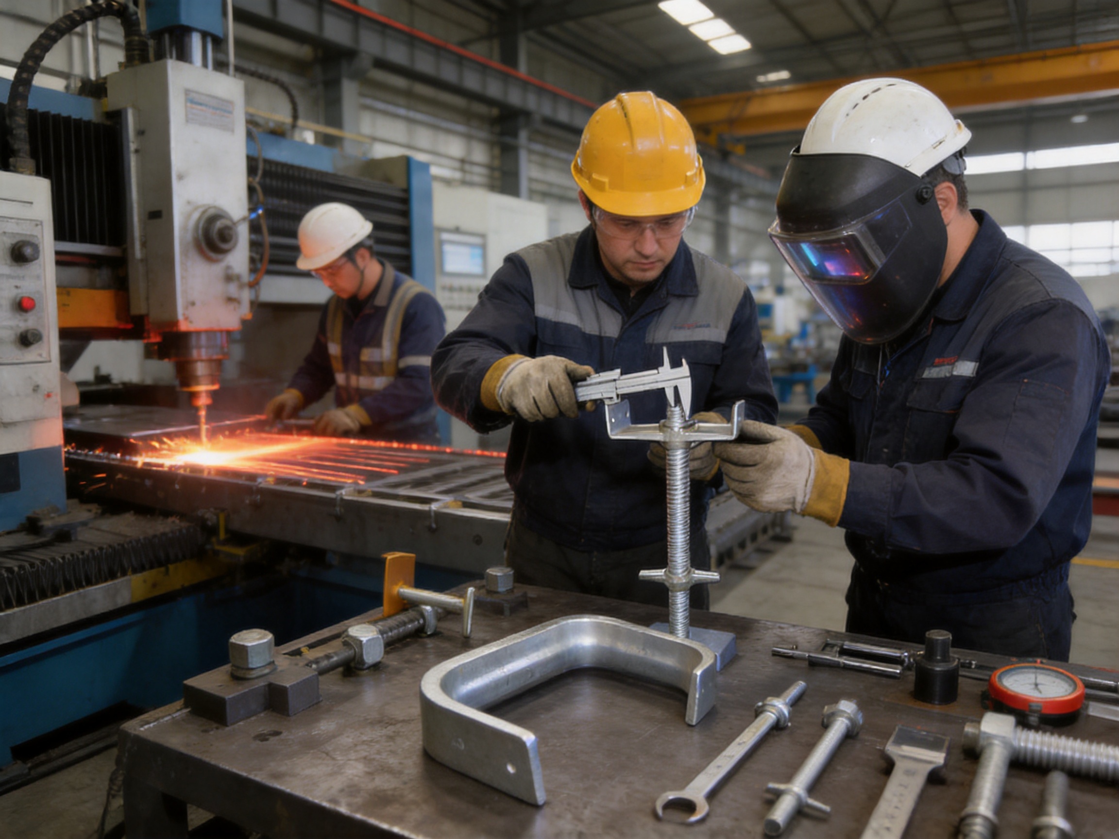
The performance of a U-head jack base depends on controlled manufacturing from raw material selection through final inspection. A component may appear simple, but its safety and service life are influenced by many production details, including steel quality, forming accuracy, thread fit, weld consistency, coating condition, and dimensional control.
Material Selection
Q235 and Q345 carbon steel are commonly selected for the major structural parts of the product. The appropriate grade depends on the design, required load, manufacturing method, and customer specification. Material certificates and incoming inspection procedures help verify the chemical and mechanical properties of the steel.
Material selection also considers the manufacturing process. The steel must have suitable ductility and forming characteristics for stamping, bending, forging, machining, or welding. Consistent material properties help reduce variation between production batches.
Steel Cutting and Blank Preparation
Steel plate, bar, tube, and other raw materials are cut into controlled blanks before forming and assembly. Advanced cutting equipment can produce repeatable dimensions and clean edges, reducing the amount of secondary correction required.
For custom orders, computer-controlled laser cutting may be used to prepare plates, brackets, reinforcement pieces, and other non-standard components. Accurate blank preparation improves assembly fit and supports consistent positioning during welding or forming.
Cut edges are inspected for excessive burrs, distortion, or heat-affected irregularities. Where required, edges are deburred, chamfered, or otherwise prepared for the next process.
Forming, Stamping, and Forging
The U-shaped head must maintain its geometry under working loads. Controlled stamping, bending, or forging processes help create the required groove width, side height, radius, and overall alignment.
Forming parameters are selected according to the material thickness and design. Excessive deformation, sharp corners, or uneven wall thickness can create stress concentration or interfere with beam seating. Production tooling and fixtures help maintain repeatability across batches.
After forming, the U-head is checked for dimensional accuracy, symmetry, cracks, surface defects, and deformation. The groove must be sufficiently open to receive the intended beam while maintaining a secure bearing condition.
Thread and Adjustment Component Production
The threaded stem is one of the most important functional parts of the jack base. Thread diameter, pitch, straightness, surface condition, and engagement length all affect adjustment performance and load transfer.
Threads may be produced through rolling, machining, or another controlled process suitable for the material and design. The selected process should provide a consistent profile and minimize damage during repeated adjustment.
Adjustment nuts and collars are manufactured to match the stem. Proper fit is essential. Excessive clearance may create movement or uneven loading, while insufficient clearance can make the mechanism difficult to operate, especially after exposure to dust or coating residue.
Threaded parts are checked for smooth engagement, visual damage, dimensional conformity, and operating torque. Sample load testing may also be conducted according to the customer’s quality plan or relevant technical requirements.
Welding and Assembly
Where welding is used, the assembly process must maintain the correct relationship between the U-head, stem, plate, handle, and other parts. Welding fixtures help prevent distortion and support repeatable positioning.
Hyson applies certified AWS and EN welding craftsmanship to suitable products and assemblies. Welding personnel, procedures, filler materials, heat input, and inspection methods should be controlled according to the applicable project requirements.
Welds are inspected for continuity, penetration, visible cracks, undercut, porosity, and unacceptable deformation. The inspection method may include visual examination and, where required, additional non-destructive testing or sample destructive testing.
After welding, components may undergo correction, grinding, cleaning, or dimensional verification. The objective is not simply to create a strong weld, but to ensure that the complete assembly is aligned and operates as intended.
Surface Treatment
Hot-dip galvanizing is used to improve corrosion resistance. Before galvanizing, components must be properly cleaned and prepared. Oil, scale, rust, welding residue, and other contaminants can affect coating quality.
After immersion in molten zinc, the component is inspected for coating continuity, adhesion, excessive buildup, bare areas, sharp drips, and thread obstruction. Threads may require protection, cleaning, or post-treatment so that the adjustment mechanism remains operational.
The specified coating thickness of at least 75 micrometers provides a substantial protective layer for typical construction environments. Actual coating thickness may vary by location and part geometry, so inspection should be carried out at representative points.
Final Quality Inspection
Final inspection may include dimensional measurement, visual inspection, thread operation testing, load testing, coating verification, and packaging review. The inspection plan should reflect the product configuration and customer requirements.
Important checkpoints include U-head width, groove depth, stem straightness, adjustment range, handle operation, overall height, coating condition, and identification marking. Products that do not meet the specified criteria should be segregated for correction or rejection.
Quality control is most effective when it is applied throughout the production process rather than only at the final stage. Incoming material inspection, process inspection, assembly checks, and final release inspection work together to reduce the risk of defects.
Advanced Manufacturing Strengths of the Supplier
Nantong Hyson Road And Bridge Formwork Co., Ltd. operates as an OEM manufacturer serving construction, infrastructure, industrial, transportation, mining, and agricultural customers. Its manufacturing capabilities extend beyond standard scaffolding accessories and include custom steel formwork, bridge formwork, ringlock scaffolding, hydraulic tunnel trolleys, steel props, structural steel assemblies, and heavy metal fabrication.
The company uses automated processing and standardized production lines to improve repeatability. Laser cutting, bending, welding, machining, forming, and coating processes can be coordinated for both standard and non-standard steel components.
This integrated capability is valuable for customers that require more than a single catalog component. For example, a contractor may need U-head jack bases together with customized steel beams, formwork frames, support towers, brackets, or prefabricated assemblies. A supplier capable of managing multiple processes can reduce the number of external interfaces and improve coordination between components.
The company reports compliance with ISO 9001 quality management practices and references international standards including BS1139 and EN74 for applicable scaffolding-related products. These standards and management systems support consistent documentation, process control, inspection, and traceability.
Hyson also reports twelve utility patents and experience supplying major infrastructure contractors, including CCCC and CRCC-related projects. Its project background includes large bridge, infrastructure, and power plant applications. Experience with such projects encourages disciplined control of dimensional accuracy, welding quality, load requirements, delivery schedules, and technical documentation.
Large-project experience can benefit U-head jack base customers in several ways. First, the supplier is familiar with the consequences of small dimensional deviations in temporary works. Second, it understands the need for stable batch quality when hundreds or thousands of components are used on one site. Third, it can support customized design and production when standard dimensions do not match a project’s formwork system.
Applications in Formwork and Temporary Works
Floor Slab Formwork
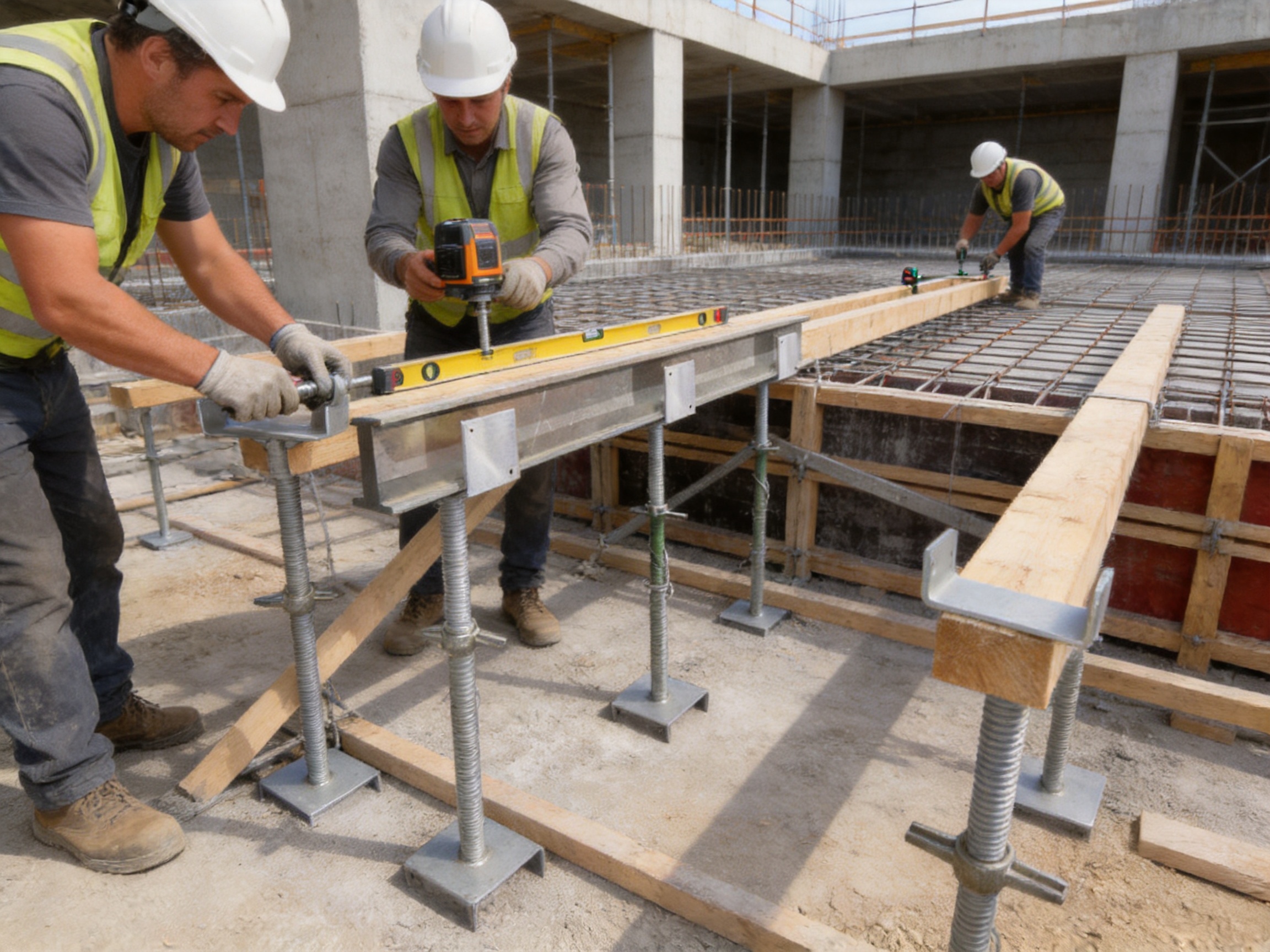
In floor slab construction, U-head jack bases are commonly installed above vertical supports to receive primary beams. The adjustable head allows the formwork elevation to be aligned with level marks and project tolerances.
When used with steel props or modular scaffold supports, the U-head creates a defined bearing point under the main beam. The support arrangement can be adjusted before secondary beams, panels, and reinforcement are completed.
Correct adjustment helps maintain slab thickness and surface flatness. It also assists in creating a uniform support grid, reducing the possibility that one area of the formwork will carry a disproportionate share of the concrete load.
Wall Formwork
Wall formwork requires control of verticality, alignment, and stability. The U-head jack base can be used as a top adjustment component where the design calls for controlled support beneath a wall formwork beam or upper frame.
Height correction helps compensate for small differences in the base, support tower, or panel arrangement. By keeping the upper support line correctly positioned, the system can help reduce panel tilting and unevenness before concrete placement.
Wall formwork must also include suitable ties, braces, walers, strongbacks, and other components required by the engineering design. The U-head jack base contributes to the support connection but does not independently stabilize the complete wall system.
Disc-Lock and Ringlock Scaffolding
Modular scaffolding systems are frequently used as temporary support towers for formwork. A U-head jack base can be installed at the top of a compatible standard to provide a supporting seat for the formwork beam.
This arrangement combines the fast assembly benefits of modular scaffolding with the fine adjustment and beam retention of a U-shaped head. It is suitable for projects where support heights vary or where the formwork needs to be aligned across a large working area.
Compatibility must be confirmed before use. The jack stem, base collar, rosette or connection interface, and support standard must be designed to work together. The scaffold tower must also be erected with the required bracing, ledger arrangement, foundation support, and working load limitations.
Precast Component Installation
Precast wall panels, floor slabs, beams, and other components often require temporary support during positioning and connection. A U-head jack base can assist in adjusting the height and maintaining the position of a temporary support beneath or beside a precast element.
The U-shaped seat can help locate a supporting beam or temporary bearer. The threaded adjustment system allows workers to make controlled corrections while checking the verticality, level, and alignment of the precast component.
Precast installation involves concentrated loads and possible impact during placement. The temporary support arrangement must therefore be designed and inspected by qualified personnel. The U-head jack base should not be used outside its rated configuration or as a substitute for permanent structural connections.
High-Altitude Work Platforms and Temporary Support Frames
In some projects, adjustable top jacks are incorporated into temporary support frames or high-level working platforms. The component can help compensate for height differences between the support frame and the supported beam or platform member.
When used in elevated applications, overall stability becomes especially important. The support system must resist lateral movement, accidental impact, wind effects where relevant, and construction loads. The U-head provides a top seating function, but the complete frame requires proper bracing and anchorage.
Installation Recommendations
Pre-Installation Inspection
Before installation, inspect each U-head jack base for bent components, damaged threads, cracks, excessive corrosion, missing parts, and coating defects. Confirm that the product dimensions and thread configuration match the support system.
Check that the U-shaped groove is free from concrete, dirt, sharp debris, and packing residue. The threaded stem should rotate smoothly through the expected adjustment range. Any component that cannot be adjusted normally should be removed from service until it is inspected.
Support Surface Preparation
The support foundation should be sufficiently strong, stable, and level for the intended load. Where an adjustable base is used below the vertical support, it should be positioned on an appropriate bearing surface or sole plate as required by the temporary works design.
Soft soil, loose fill, standing water, damaged slabs, or unsupported edges can reduce system stability. A U-head jack base cannot correct inadequate ground support. The base and vertical support arrangement must be evaluated as a complete load path.
Correct Beam Seating
Place the formwork beam centrally within the U-shaped groove. Avoid supporting the beam on one edge of the head or allowing the beam to rest diagonally unless the system has been specifically designed for that condition.
Confirm that the beam is fully seated and that adjacent supports are aligned. If a beam is not correctly positioned, adjustment alone will not create a safe connection.
Height Adjustment
Rotate the handle or adjustment nut gradually. Make small corrections while checking the formwork level, line, and verticality. Avoid sudden lifting, excessive force, or adjustment while the component is carrying an unintended eccentric load.
After reaching the correct elevation, verify that the threaded engagement remains sufficient. Excessive extension can reduce stability and load capacity. The allowable extension should follow the product’s technical data and the approved support design.
System Bracing and Final Checks
Install all required horizontal ledgers, diagonal braces, ties, couplers, and stabilizing components before loading the formwork. Check that the vertical supports are plumb and that the U-heads are not subjected to unnecessary side loading.
Before concrete placement, inspect the entire support system. Look for gaps, loose connections, damaged threads, unsupported beam ends, uneven base conditions, and interference with reinforcement or embedded items.
During pouring, monitor the formwork for unexpected settlement, movement, vibration, or deformation. If abnormal movement occurs, stop work and follow the project’s emergency and inspection procedure.
Maintenance, Storage, and Service Life
Proper maintenance helps preserve adjustment performance and extend product life. After use, remove concrete, mud, and debris from the U-head and threaded parts. Hardened concrete should not be removed by methods that deform the groove or damage the thread.
Inspect the galvanized coating for severe scratches, impact damage, or exposed steel. Minor damage may be treated according to the coating repair procedure. Components showing deep corrosion, cracks, thread deformation, or permanent bending should be removed from service.
Store U-head jack bases in a dry, ventilated area where possible. Avoid direct contact with standing water, corrosive chemicals, and incompatible metals. Keep threaded parts protected from heavy impact during transport and stacking.
Lubrication may be applied to the threaded mechanism when recommended by the manufacturer. The lubricant should be compatible with the construction environment and should not create a slippery surface at the beam seat or connection interface.
Service life depends on loading, adjustment frequency, environment, handling, maintenance, and inspection quality. A galvanized component may remain serviceable for a long period, but it should never be reused automatically without condition assessment.
Customization Options for OEM Projects
Different formwork systems may require different head widths, groove depths, stem lengths, thread specifications, handle configurations, connection plates, and surface treatments. OEM manufacturing allows the U-head jack base to be adapted to project requirements rather than forcing the customer to redesign the entire support system.
Potential customization parameters include overall height, adjustment range, U-head dimensions, steel grade, thread diameter, thread pitch, handle size, galvanizing specification, paint or duplex coating, packaging format, and product marking.
Customers should provide technical drawings, loading information, support system details, expected quantities, working environment, and relevant standards when requesting a customized solution. These details allow the manufacturer to assess the design and identify possible interference with existing formwork or scaffolding components.
For large projects, sample approval and first-article inspection can be arranged before mass production. This process helps confirm the fit, adjustment performance, dimensions, appearance, and packaging requirements.
Customized production is especially useful for bridge construction, tunnel projects, infrastructure upgrades, industrial plants, precast yards, and contractors with proprietary formwork systems. The same manufacturing resources used for heavy steel fabrication can also support custom brackets, frames, beams, and welded assemblies required around the U-head jack base.
Quality and Safety Considerations
Temporary works products must be selected and used according to an engineered design. A stated product capacity is not a universal permission to apply the component at that load in every condition. Effective height, eccentric loading, support spacing, foundation strength, system bracing, connection compatibility, and construction sequence all influence the actual safe working condition.
Users should request technical data, inspection records, material information, and applicable test documentation when required by the project. Product markings and batch records support traceability, especially for major infrastructure projects.
The U-head jack base should not be modified by drilling, cutting, welding, or grinding without written technical approval. Unapproved modifications may change the load path, reduce cross-sectional area, damage corrosion protection, or create stress concentration.
Workers should receive instruction on assembly, adjustment, inspection, and removal. They should understand the difference between the adjustment mechanism and the locking or load-bearing condition. The jack should never be used as a lifting device unless it has been specifically designed, rated, and approved for lifting.
During concrete placement, loading should follow the planned sequence. Rapid or uneven pouring can create dynamic and eccentric loads that exceed assumptions. The formwork support arrangement should be monitored throughout the operation.
Why Choose an Integrated Heavy Steel Manufacturer?
Buying a U-head jack base from a supplier with broader steel manufacturing capability can offer advantages beyond the component itself. Formwork and scaffolding systems are interconnected. A support accessory must fit the beam, prop, scaffold, bracket, and frame with which it will be used.
An integrated manufacturer can review these relationships more effectively. It can cut and form steel components, produce welded assemblies, modify support interfaces, and coordinate dimensions across a complete temporary works package.
Nantong Hyson Road And Bridge Formwork combines formwork production, scaffolding manufacturing, laser cutting, bending, welding, and heavy steel fabrication. This allows the company to serve customers requiring individual accessories as well as complete or partially integrated support solutions.
The company’s experience with major bridge and infrastructure projects provides an understanding of demanding site requirements, including high load, repeatable quality, dimensional control, delivery coordination, and documentation. Its stated ISO 9001 quality management approach supports process consistency, while AWS and EN welding practices contribute to controlled structural fabrication.
For OEM customers, the combination of design communication, manufacturing capacity, surface treatment, inspection, and export packaging can simplify procurement. It can also help reduce the technical risk associated with sourcing related components from several unrelated suppliers.
Frequently Asked Questions
What is the main purpose of a U-head jack base?
The main purpose is to provide an adjustable top connection between a vertical support and formwork. Its U-shaped head supports and locates the formwork beam, while the threaded mechanism allows workers to fine-tune the support height.
How is it different from an adjustable base jack?
An adjustable base jack is normally installed at the bottom of a support to level the foundation or floor contact. A U-head jack base is installed at the top and is designed to receive and stabilize a formwork beam or rib.
What adjustment range is available?
The described product has an adjustment range of approximately 30 mm to 150 mm. The final usable range depends on the product configuration, thread engagement, extension condition, and approved technical documentation.
What is the adjustment accuracy?
The stated adjustment accuracy can reach approximately plus or minus 0.5 mm under suitable operating conditions. Actual field accuracy also depends on installation quality, measurement equipment, thread condition, support stability, and the precision of the surrounding formwork system.
What load can one U-head jack base support?
The stated capacity range is approximately 80 kN to 120 kN per support. The applicable working load must be confirmed for the exact model and complete support arrangement because extension, eccentricity, bracing, foundation conditions, and load direction affect performance.
Which materials are used?
The major structural components can be manufactured from Q235 or Q345 high-strength carbon steel, subject to the product design and customer requirements. Material certificates may be provided according to the applicable quality plan.
Is the product suitable for ringlock or disc-lock scaffolding?
It can be configured for use with compatible modular scaffolding systems, including disc-lock or ringlock arrangements. The interface dimensions and load requirements must be checked before installation.
Can the U-head jack base be used for wall formwork?
Yes, it can be used as a top adjustment component for suitable wall formwork support arrangements. The complete wall formwork system still requires proper ties, braces, walers, strongbacks, and engineering verification.
Is hot-dip galvanizing available?
Yes. The described product uses hot-dip galvanizing with a stated coating thickness of at least 75 micrometers for the applicable configuration. The coating improves resistance to humidity and common construction-site exposure.
Can the dimensions be customized?
OEM customization may include U-head dimensions, stem length, thread specifications, adjustment range, handle design, connection interfaces, material grade, coating, marking, and packaging. Customers should submit drawings and project requirements for technical review.
Can the component replace system bracing?
No. The U-head jack base provides top support and adjustment, but it does not replace diagonal bracing, horizontal ledgers, ties, anchors, or other stability components required by the formwork design.
How should used components be inspected?
Inspect the U-head for deformation and cracks, the stem for bending, the threads for damage, the handle for secure operation, and the galvanized coating for severe corrosion or exposed steel. Components with structural damage or unreliable adjustment should be removed from service.
What information should be supplied for an OEM quotation?
Useful information includes drawings, head dimensions, thread size, overall and adjustment heights, required load, quantity, support system type, surface treatment, applicable standards, packaging requirements, delivery location, and any inspection or documentation requirements.
Conclusion
The U-head jack base is a specialized support accessory that improves the connection between formwork and vertical support systems. Its main advantages are the secure U-shaped beam seat, precise threaded height adjustment, broad compatibility, high-strength steel construction, corrosion-resistant surface treatment, and straightforward operation.
Its value is most evident in applications where formwork accuracy and support stability must be achieved together. Floor slab formwork, wall formwork, modular scaffold towers, precast installation, and temporary support frames can all benefit from a reliable top-adjustable connection.
Compared with a basic adjustable base, the U-head jack base provides direct top fitting. Compared with a standard steel prop, it offers a more controlled beam seat and fine-adjustment function. Compared with a flat head, its groove provides improved positioning and contact for compatible formwork members.
Manufacturing quality remains essential. Material selection, precision cutting, forming, thread production, welding, galvanizing, dimensional inspection, and load verification all contribute to reliable performance. An experienced OEM manufacturer with integrated steel fabrication capabilities can provide not only the jack base, but also technical coordination and customized support for related formwork and structural components.
When selected according to engineering requirements and installed with proper bracing and inspection, the U-head jack base can help construction teams improve formwork levelness, wall verticality, pouring accuracy, installation efficiency, and temporary works safety.
References
1. ISO 9001, Quality Management Systems — Requirements.
2. BS 1139, Metal Scaffolding — applicable product and dimensional guidance.
3. EN 74, Couplers, Spigot Pins and Baseplates for Use in Falsework and Scaffolds — applicable connection and performance guidance.
4. AWS Structural Welding Code — Steel, applicable welding quality and fabrication practices.
5. General principles of temporary works design, formwork stability, load transfer, and construction-site inspection.
6. Manufacturer-provided product specifications for U-head jack bases, including adjustment range, material grade, coating thickness, and rated support capacity.
7. Project-specific formwork drawings, temporary works calculations, installation procedures, and safety inspection requirements.
Product: U-head Jack Base



- Location
- Group 3, Fangzhuang Village, Rucheng Subdistrict, Rugao City, Nantong, Jiangsu, China
- Follow us
- Phone
- +86-13646196162
- info@hysonindustry.com
