 +86-13646196162
 info@hysonindustry.com




 русский
 عربى



Fork Head Support for High-Load Formwork and Scaffolding Systems
 2026.10.27
Content
- 1 1. The Role of a Fork Head Support in Formwork Engineering
- 2 2. Four-Forked Geometry for Multi-Point Load Distribution
- 3 3. Precision Height Adjustment and Construction Tolerance Control
- 4 4. High-Strength Steel Construction
- 5 5. Anti-Slip and Anti-Drop Performance
- 6 6. Corrosion Protection for Construction Environments
- 7 7. Comparison with Other Support Accessories
- 8 8. Manufacturing Process and Quality Control
- 9 9. Manufacturing Strengths for OEM and Custom Orders
- 10 10. Applications in Large Flat Formwork
- 11 11. Applications in Floor Slab and Roof Formwork
- 12 12. Applications in Large Venues and Infrastructure Projects
- 13 13. Applications in Precast Concrete Casting
- 14 14. Installation Procedure
- 15 15. Safety and Maintenance Recommendations
- 16 16. Advantages for Contractors and Project Owners
- 17 17. Recommended Procurement Information
- 18 18. Frequently Asked Questions
- 18.1 Q1: What is the main purpose of a Fork Head Support?
- 18.2 Q2: How is it different from a U-shaped adjustable support?
- 18.3 Q3: Can the product be used with steel props?
- 18.4 Q4: What is the adjustment range?
- 18.5 Q5: What load can one Fork Head Support carry?
- 18.6 Q6: What steel grades are used?
- 18.7 Q7: Is the product corrosion-resistant?
- 18.8 Q8: Can the fork dimensions be customized?
- 18.9 Q9: Can it replace bracing or a tripod?
- 18.10 Q10: How should the product be maintained?
- 18.11 Q11: What quality documents can be requested?
- 18.12 Q12: Is the Fork Head Support suitable for precast concrete?
- 19 19. Conclusion
- 20 References
- 21 Product: Fork Head Support
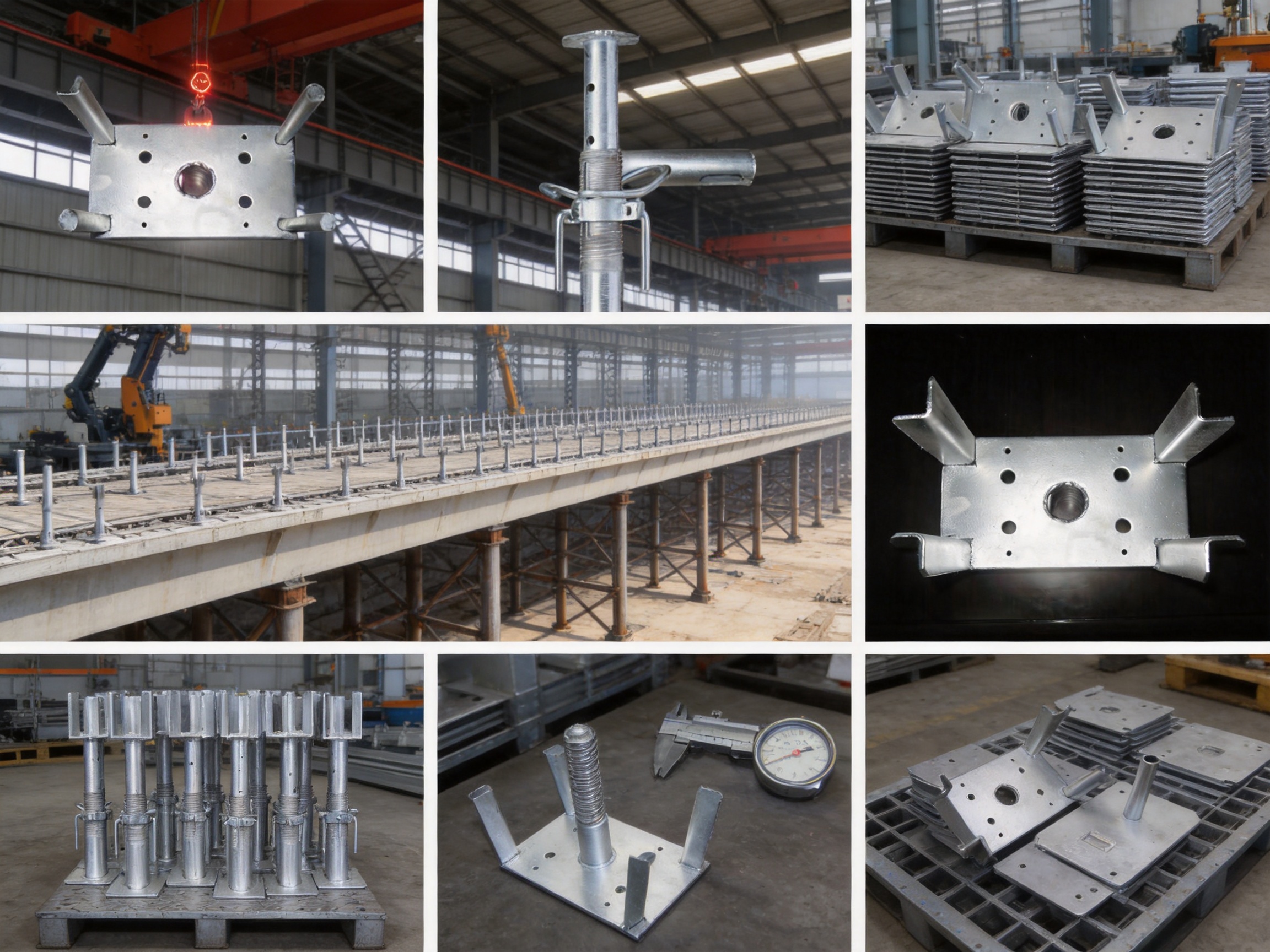
Fork Head Support is a specialized top support component developed for formwork, floor slab support, scaffolding, and heavy-duty temporary works. It is installed at the upper end of a supporting system and creates a stable interface between vertical steel supports and the formwork ribs, primary beams, or secondary beams above. By combining a four-forked head, precision height adjustment, anti-slip contact surfaces, and high-strength steel construction, it helps transfer vertical loads safely and evenly while maintaining the required elevation and levelness of the formwork.
In large concrete construction projects, the quality of the top connection between the support system and the formwork has a direct influence on stability, concrete surface quality, construction speed, and worker safety. A supporting post may have sufficient compression capacity, but the complete system can still perform poorly if the upper contact point is unstable, difficult to adjust, or unable to distribute loads over the formwork ribs. The Fork Head Support addresses this important interface problem by offering multiple contact points and controlled fine adjustment in one compact component.
The product is designed for use with steel props, adjustable bases, heavy-duty independent supports, and other compatible formwork support members. It is suitable for large-area floor slab formwork, roof formwork, ground formwork, precast component casting, and other applications where a reliable top connection is essential. Its configuration can be adapted to different formwork rib dimensions and project requirements through customized manufacturing.
1. The Role of a Fork Head Support in Formwork Engineering
Formwork systems temporarily carry the weight of fresh concrete, reinforcement, workers, construction equipment, and the formwork materials themselves. These loads must be collected by the formwork skin and transferred through secondary beams, primary beams, support heads, vertical props, adjustable bases, and finally to the ground or permanent structure. Every connection in this load path must remain stable throughout installation, concrete placement, vibration, and curing.
The upper support point is particularly important because it connects horizontal or inclined formwork members to vertical supports. A simple flat plate may provide insufficient restraint. A narrow contact surface can create concentrated pressure on the beam. A conventional U-shaped support may hold one beam but offer limited engagement with several intersecting members. In contrast, a forked top support can engage formwork ribs or beams from multiple directions, improving contact and reducing the risk of local movement.
The four-forked design provides a practical solution for formwork systems in which primary and secondary members cross or are arranged in a regular grid. The head can receive the relevant ribs, help maintain their position, and distribute vertical reaction forces through several contact areas. This configuration is especially valuable in large planar formwork, where small deviations in elevation or beam alignment can become visible over a large concrete surface.
In addition to supporting the load, the component provides height adjustment. The threaded mechanism allows installers to correct differences caused by uneven ground, variations in support member length, formwork thickness, or construction tolerances. Instead of dismantling the support frame or inserting improvised packing materials, workers can make controlled adjustments using the integrated rotating handle.
This combination of load transfer, beam engagement, and height adjustment makes the Fork Head Support more than a simple bracket. It functions as a precision interface between the structural support system and the temporary formwork assembly.
2. Four-Forked Geometry for Multi-Point Load Distribution
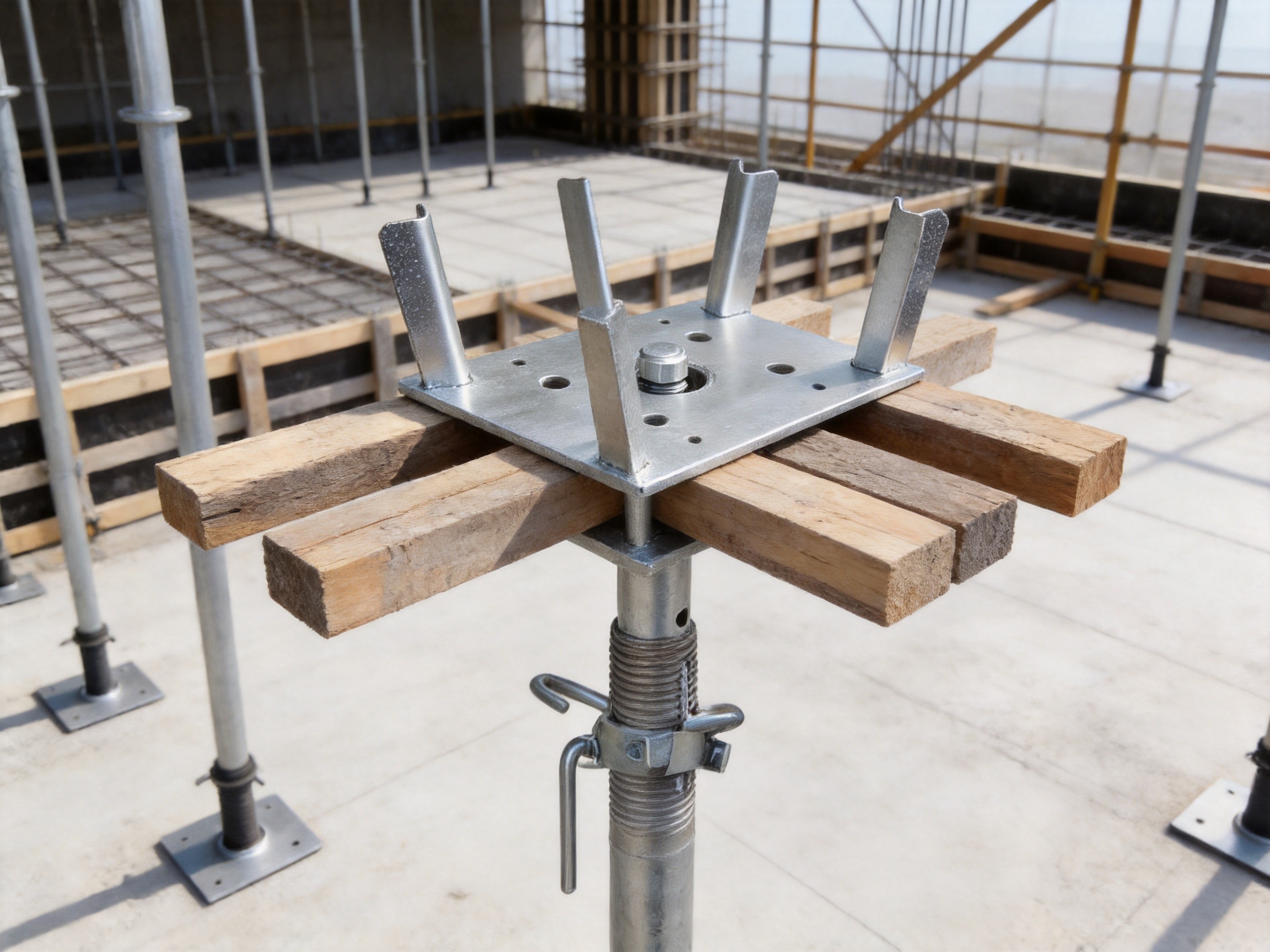
The main distinguishing feature of the product is its integrated four-corner fork design. Each fork creates a defined receiving position for formwork ribs or beam members. When the head is correctly installed, the supported members are seated within the forked areas rather than resting on a single uncontrolled point.
Multi-point support offers several engineering and practical benefits. First, it can distribute the vertical reaction across a wider contact arrangement. This helps reduce excessive localized stress on the supported beam and limits the possibility of indentation, twisting, or local deformation. Second, the forked geometry improves positional retention. The supported members are less likely to move laterally during assembly or concrete placement when they are properly seated within the head. Third, the arrangement can accommodate intersecting or closely spaced members more effectively than a single-slot support.
A traditional U-shaped support is useful when the supported member has a predictable width and must be retained in one continuous groove. However, its contact is primarily concentrated around one channel. The four-forked configuration is intended for situations where multiple ribs, crossing beams, or varied member arrangements require more adaptable engagement. It provides separate receiving points and can improve the connection between the support head and the formwork grid.
The geometry also benefits installation. Workers can identify the intended seating locations visually and position the formwork beams without complicated temporary fastening. When combined with anti-slip pads or compatible bearing surfaces, the forks help prevent beam displacement during ordinary handling and concrete pouring operations.
Correct use remains essential. The forks must fully engage the intended formwork members, and the supported beams must not rest on sharp edges, partial contact points, or unstable packing pieces. The support system should be assembled according to the project design, including the required spacing, bracing, load limits, and ground preparation.
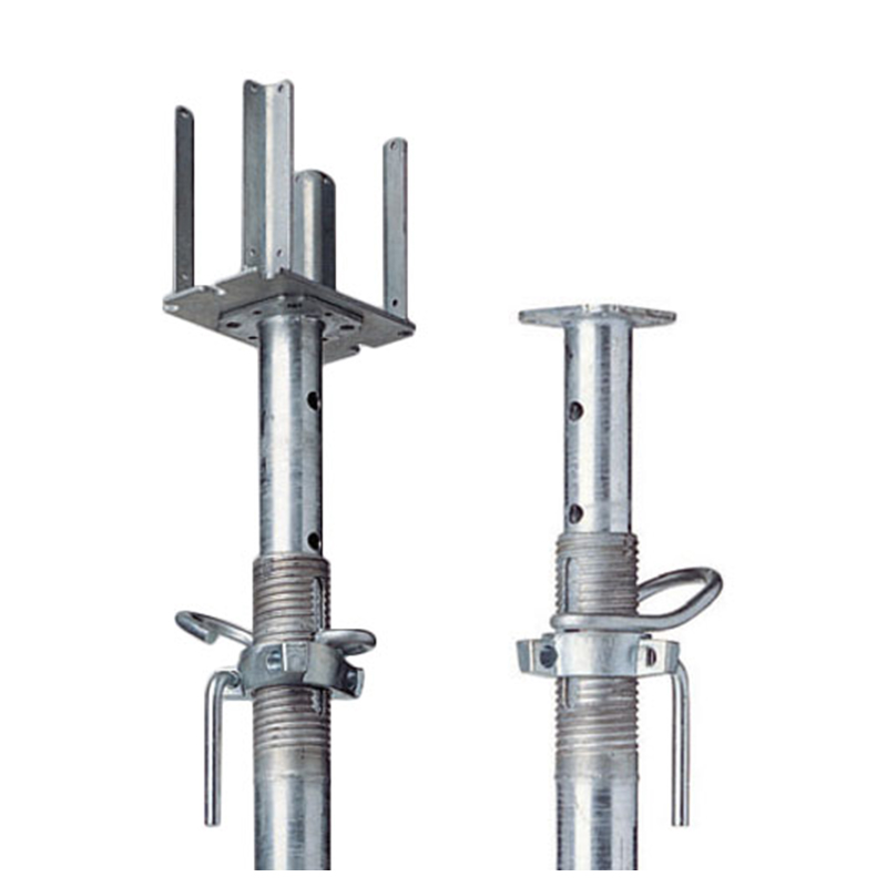
Fork Head Support
3. Precision Height Adjustment and Construction Tolerance Control
Formwork projects rarely have perfectly uniform conditions. Slab thickness may vary between zones, the supporting surface may have minor level differences, and steel components may have normal manufacturing tolerances. If these variations are not corrected, the upper surface of the formwork can become uneven. In concrete construction, such unevenness may affect slab thickness, finished floor levels, drainage falls, architectural appearance, and the amount of later repair work.
The Fork Head Support incorporates a precision threaded adjustment mechanism intended for controlled height correction. The stated adjustment range is 40 mm to 180 mm, depending on the selected configuration, and the adjustment accuracy can reach approximately ±0.5 mm under suitable installation conditions. This adjustment capacity allows the head to compensate for support height deviations and accommodate different formwork assemblies without requiring extensive modification to the primary support frame.
The fine-thread structure supports gradual movement rather than abrupt changes. A worker can rotate the handle and raise or lower the support head in small increments until the formwork reaches the specified elevation. This is especially useful when a large slab area must be brought to a consistent level. A controlled adjustment process is easier to repeat and inspect than the use of loose timber wedges, unapproved steel packing, or irregular improvised materials.
Fine adjustment also helps coordinate the support head with the formwork design. If the formwork skin, secondary ribs, and primary beams have different dimensions from one project to another, the height of the head can be set to achieve the correct bearing relationship. This reduces the need to carry multiple support lengths and allows the same general support system to serve a broader range of construction conditions.
Height adjustment should be completed before loading whenever possible. After the formwork and reinforcement have been installed, the system should be checked again for levelness, vertical alignment, full seating, and signs of instability. The adjustment mechanism should not be used to compensate for an overloaded, damaged, or incorrectly braced support arrangement. Its purpose is precision positioning, not replacement of structural design or temporary works engineering.
4. High-Strength Steel Construction
The Fork Head Support is manufactured from high-strength carbon steel grades such as Q235 or Q345, according to the required specification and application. These materials provide a practical balance of strength, weldability, forming performance, and cost for construction support components.
The fork-shaped head is produced through forming processes that may include stamping, forging, cutting, bending, and reinforcement assembly. Integrally formed or carefully reinforced sections are better able to resist compression and deformation than thin, loosely assembled parts. Reinforcing ribs increase stiffness in areas exposed to vertical reaction forces and help maintain the geometry of the head under load.
The stated single-support capacity is approximately 90 kN to 130 kN, depending on the product configuration, material, dimensions, manufacturing standard, and test conditions. The actual allowable working load must be confirmed for each project because capacity depends not only on the head itself but also on the connected steel prop, thread condition, support spacing, eccentricity, bracing, bearing surface, and overall system design.
High compressive resistance is essential when the product is used beneath large slabs, thick concrete sections, transfer structures, industrial buildings, or large public venues. A weak head can deform even when the vertical prop below remains intact. Such deformation may reduce contact, cause eccentric loading, and increase the risk of progressive instability. The reinforced fork head is designed to retain its shape and maintain a reliable interface under demanding temporary loads.
The support should nevertheless be inspected before every use. Bent forks, cracked welds, damaged threads, severe corrosion, missing handles, excessive wear, or distorted bearing surfaces are reasons to remove the component from service. A nominal load rating does not apply to a visibly damaged or incorrectly installed product.
5. Anti-Slip and Anti-Drop Performance
Load capacity alone does not guarantee stability. Formwork members can shift horizontally during assembly, reinforcement placement, worker movement, concrete discharge, or mechanical vibration. A support head must therefore help retain the supported components in their intended position.
The fork grooves are precision-finished to correspond with the dimensions of the supported ribs or beams. The defined receiving shape reduces uncontrolled movement and helps keep the formwork members centered over the vertical support. Anti-slip pads or compatible bearing surfaces can further increase friction and protect the contact areas from direct metal-to-metal damage.
The anti-drop function is particularly useful during preliminary assembly. When a beam is placed into the forked head, the surrounding geometry provides a degree of retention before the entire formwork grid has been completed. This can simplify installation and reduce the likelihood of accidental displacement caused by light contact or normal handling. The head should not be treated as a substitute for required ties, braces, clamps, or other project-specific restraint systems, but it can improve the security of the primary connection.
A stable connection also supports better concrete quality. If a beam moves during pouring, the formwork skin may deflect, joints may open, or slab thickness may vary. Keeping the support grid aligned helps preserve the intended geometry until the concrete has gained adequate strength.
6. Corrosion Protection for Construction Environments
Formwork and scaffolding components are frequently exposed to moisture, cement slurry, outdoor rain, storage humidity, and repeated handling. Bare carbon steel can corrode rapidly in these conditions, especially around threaded areas, welds, corners, and surfaces where water or cement residue accumulates.
The Fork Head Support can be supplied with hot-dip galvanized surface protection. The stated coating thickness is at least 75 micrometers for the applicable configuration. Hot-dip galvanizing creates a metallurgically bonded zinc coating that protects the underlying steel through barrier action and sacrificial protection. This is suitable for many construction environments and can extend service life when the product is stored, handled, and maintained correctly.
Galvanized surfaces are valuable for rental fleets and reusable temporary works equipment because they reduce the rate of deterioration between projects. A durable finish also lowers the frequency of repainting and helps maintain a clear visual condition for inspection. However, deep cuts, severe impact damage, or prolonged exposure to aggressive chemicals can compromise the coating. Damaged areas should be assessed and repaired using an appropriate zinc-rich treatment where permitted by the maintenance procedure.
Threads require special attention. Cement paste should not be allowed to harden on the adjustment mechanism because it can prevent smooth rotation and damage the thread. After use, the product should be cleaned, dried, and inspected. Lubrication should be compatible with the galvanized surface and the project’s safety requirements.
7. Comparison with Other Support Accessories
Different support accessories serve different functions. Selecting the correct component depends on the formwork arrangement, required adjustment range, load, connection geometry, and installation method. The Fork Head Support is not intended to replace every type of bracket or base; its advantage is its specialized role at the top of a formwork support system.
| Support component | Primary function | Typical connection | Principal advantage | Key limitation compared with a fork head |
|---|---|---|---|---|
| Fork Head Support | Top support for formwork ribs and beams | Four-forked multi-point bearing | Even load distribution, secure beam engagement, and precise height adjustment | Must be matched to the formwork member dimensions and system load |
| U-shaped adjustable support | Top receiving bracket for a single beam or member | Continuous U-shaped groove | Simple beam retention and straightforward installation | Generally offers fewer contact points and less flexible engagement with intersecting ribs |
| Adjustable base | Ground leveling and bottom adjustment | Base plate with threaded stem | Compensates for uneven supporting surfaces | It does not provide the specialized upper connection required for formwork ribs |
| Heavy-duty steel prop | Independent vertical load-bearing | Telescopic tube and adjustment collar | Strong vertical support and reusable construction | Requires a suitable top head to connect effectively with the formwork |
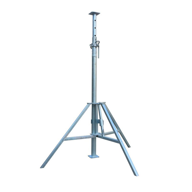
| Tripod | Temporary lateral stabilization | Three-leg bracing around a vertical support | Quick temporary positioning during assembly | It is not a primary multi-point top support for formwork beams |
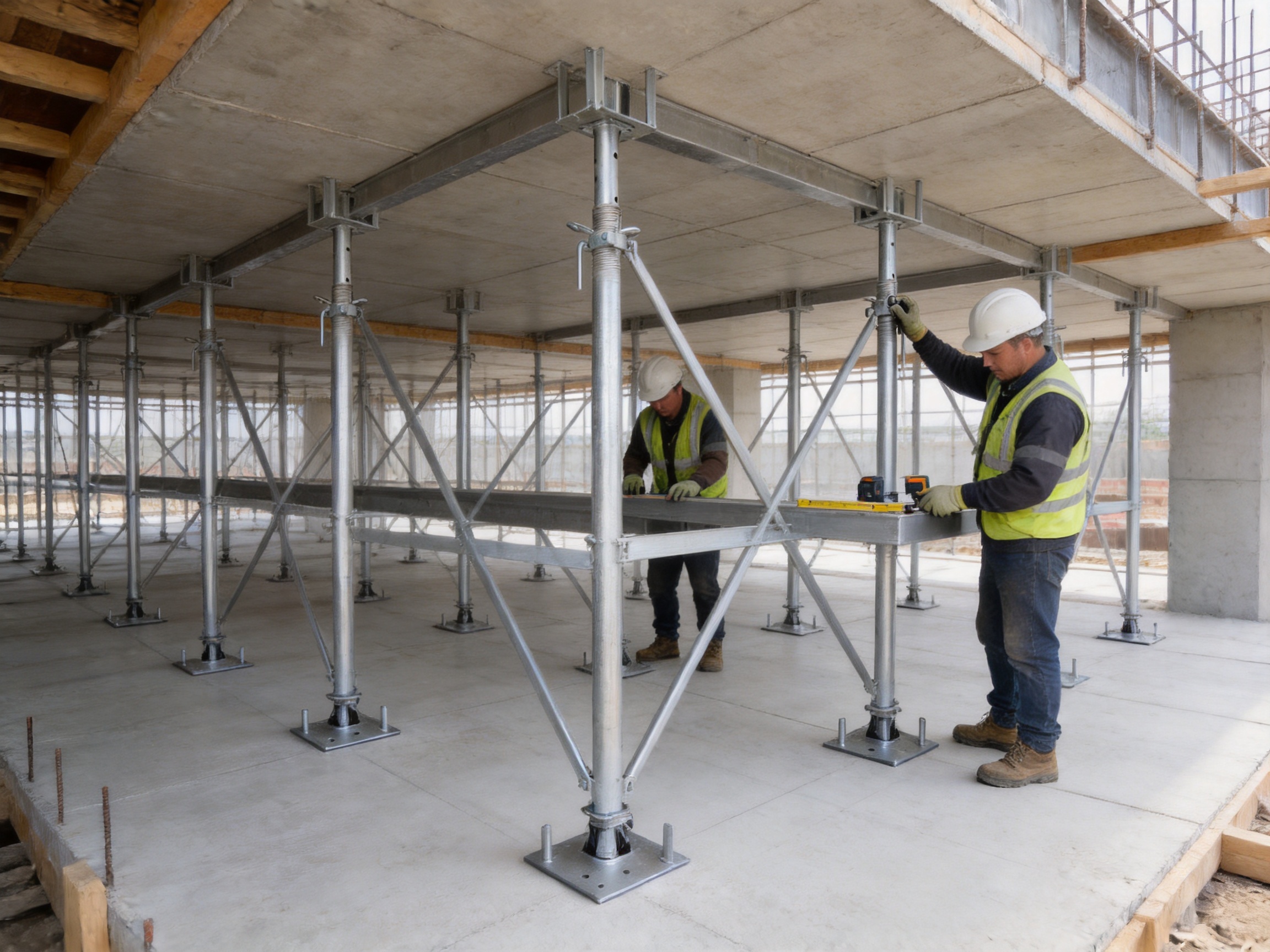
The product is particularly effective when used together with an adjustable base and a steel prop. The base corrects ground-level differences, the prop carries the main vertical load, and the fork head creates the upper formwork connection. This division of functions produces a more controlled support chain than asking one component to perform every task.
Compared with a simple flat plate, the forked design provides better lateral definition and more predictable beam seating. Compared with a fixed head, the threaded adjustment allows greater flexibility during leveling. Compared with loose packing materials, the engineered connection provides a repeatable and inspectable solution.
8. Manufacturing Process and Quality Control
The reliability of a fork head depends heavily on manufacturing accuracy. The receiving grooves must be correctly formed, the threaded mechanism must rotate smoothly, the reinforcement must be properly positioned, and the finished assembly must meet dimensional and load requirements. A professional heavy-metal fabrication process therefore uses controlled production stages rather than relying solely on manual fitting.
8.1 Engineering Review and Material Selection
Production begins with a review of the product drawing, required dimensions, material grade, load requirement, surface treatment, and connection details. The manufacturer evaluates the intended formwork member size and confirms whether the standard design is suitable or whether an OEM variation is required.
Material certificates and incoming inspection records can be used to verify the steel grade and thickness. Q235 and Q345 carbon steel are widely used because they combine suitable mechanical performance with good processing characteristics. For special projects, alternative materials, thicker sections, modified reinforcement, or additional testing may be specified.
8.2 CNC Laser Cutting and Plate Preparation
Modern CNC laser cutting equipment can produce accurate plate and reinforcement components from digital drawings. Laser cutting supports clean profiles, repeatable dimensions, and efficient production of small or large batches. It is particularly useful for custom steel components in which the fork outline, handle plates, reinforcement ribs, or mounting parts must be produced to a controlled shape.
Accurate cutting reduces the amount of secondary trimming and helps maintain consistency between batches. It also supports rapid customization for different fork widths, thread sizes, plate dimensions, and connection details. Cut edges are inspected and, where necessary, deburred before forming or welding.
8.3 Stamping, Forging, and Forming
The forked head may be shaped through stamping, forging, or a combination of forming operations. These processes create the receiving geometry and can improve repeatability compared with purely manual fabrication. Forming dies and dedicated fixtures help maintain the intended fork spacing and angle.
Where high local stress is expected, reinforcement ribs are added to improve stiffness. The manufacturing team must control forming pressure, alignment, and springback so that the finished component accepts the specified formwork members without excessive looseness or forced installation.
8.4 Welding and Assembly
Welding joins the fork head, reinforcing ribs, threaded components, handle parts, and other structural elements. Qualified welding procedures and trained operators are important because poor weld quality can reduce load capacity even when the base material is adequate.
The manufacturing capability includes welding practices aligned with recognized AWS and EN requirements, subject to the project specification and applicable inspection plan. Welding may include visual inspection, dimensional checks, and additional non-destructive testing where required. Welds should be free from unacceptable cracks, lack of fusion, excessive undercut, serious porosity, and other defects that could compromise the product.
8.5 Thread Processing and Functional Testing
The adjustment thread is a critical functional part. It must have suitable pitch, strength, alignment, and surface condition. During assembly, the thread is checked for smooth movement through the complete adjustment range. The rotating handle must be firmly attached and usable without specialized tools.
Functional checks may include measurement of adjustment range, inspection of thread engagement, confirmation of stop positions, and verification that the head remains stable at representative settings. Products intended for demanding projects may be subjected to load tests or batch sampling according to the agreed quality plan.
8.6 Galvanizing and Final Inspection
After fabrication and preparation, the product can be hot-dip galvanized. Surface cleanliness, drainage, venting, immersion, and coating thickness all influence the final result. The finished coating is examined for coverage, adhesion, visible defects, and thickness. The stated minimum coating thickness of 75 micrometers should be understood together with the relevant project standard and inspection method.
Final inspection includes dimensional verification, visual examination, thread operation, fork alignment, weld condition, surface treatment, identification marking, and packaging. Components that do not meet the required criteria should be reworked or rejected rather than mixed with approved stock.
9. Manufacturing Strengths for OEM and Custom Orders
Large construction projects frequently require non-standard dimensions. Formwork ribs may differ in width, beam spacing may vary, and local design conditions may require a special adjustment range or additional reinforcement. A supplier with integrated cutting, bending, forming, welding, and finishing capabilities can respond more effectively than a supplier that only assembles imported standard parts.
Nantong Hyson Road And Bridge Formwork Co., Ltd. operates as a manufacturer of custom formwork, scaffolding, steel props, steel structures, and OEM metal components. Its production resources include advanced laser cutting equipment, standardized manufacturing lines, steel plate processing, bending, welding, and finishing capabilities. This integrated approach supports the production of ready-to-install components rather than unfinished pieces requiring extensive work at the construction site.
The company reports experience with AWS and EN welding practices, ISO 9001 quality management, and products aligned with standards such as BS1139 and EN74 where applicable. It also reports 12 utility patents and experience supplying large infrastructure and industrial projects. These capabilities are relevant to fork head production because they support repeatability, traceability, process control, and adaptation to project-specific requirements.
OEM cooperation may include drawing review, prototype development, sample approval, load requirement analysis, material selection, production inspection, packaging, and batch delivery. A customer can provide a formwork layout, beam dimensions, target loading, adjustment range, or connection detail, and the engineering team can evaluate a suitable design.
For international buyers, manufacturing strength is also reflected in communication and documentation. Important documents may include material certificates, inspection reports, dimensional records, galvanizing records, welding procedure information, product drawings, packing lists, and operating instructions. The exact documentation package should be agreed before production begins.
10. Applications in Large Flat Formwork
Large flat formwork is common in floor slabs, roofs, podium decks, industrial floors, bridge-related structures, and broad concrete platforms. These projects require many support points to work together at a consistent elevation. The Fork Head Support is installed at the top of vertical steel props or compatible support columns, where its forks engage the primary and secondary formwork members.
The multi-point head helps spread the reaction from the formwork grid into the vertical support. Its adjustment mechanism allows workers to bring the formwork to the specified level before reinforcement and concrete placement. When the support spacing and bracing are correctly designed, the system can provide a stable base for large-area pouring operations.
Large slabs often magnify small errors. A few millimeters of variation at one support point may lead to visible differences across a wide surface. Fine adjustment therefore contributes not only to structural support but also to the quality of the finished concrete surface. The head can be used during initial leveling and final checking to help achieve consistent elevation.
11. Applications in Floor Slab and Roof Formwork
In high-rise buildings, factories, warehouses, and commercial structures, the product can support floor slab formwork that includes a grid of primary beams, secondary ribs, and panels. The steel props below carry the vertical loads while the fork heads retain the beam arrangement at the top.
For roof formwork, the same principle applies, although the support arrangement may include additional slope requirements, edge conditions, or temporary bracing. The adjustment range helps adapt the support head to sloping or stepped zones when the design permits such use. The project engineer must confirm that the head remains properly seated and that any inclined load components are adequately restrained.
Because floor and roof formwork may be poured in repeated cycles, durability and ease of operation are valuable. Galvanized surfaces resist ordinary construction moisture, while the rotating handle allows rapid adjustment during the preparation of each pour. Reusable components can reduce long-term equipment costs when they are cleaned, inspected, and stored correctly.
12. Applications in Large Venues and Infrastructure Projects
Stadiums, exhibition centers, transport facilities, power plants, and other large venues often contain broad structural zones with high formwork loads. Their support arrangements may include different beam layouts, large spans, varied slab thicknesses, and complex interfaces with permanent structures.
The forked head is suitable for such conditions when its dimensions and capacity match the project requirements. Its ability to engage different formwork ribs can simplify the construction of wide support grids. The adjustment mechanism is useful where the formwork must maintain tight level tolerances across large distances.
Infrastructure projects also demand reliable documentation and supply coordination. A manufacturer experienced in bridge formwork, hydraulic tunnel trolleys, industrial steel structures, and heavy metal fabrication can apply project-based quality controls to temporary support accessories. Manufacturing consistency is particularly important when thousands of similar components are needed for phased construction.
13. Applications in Precast Concrete Casting
Precast concrete production requires dimensional consistency because the form determines the final geometry of each component. The Fork Head Support can be used in temporary casting support systems for large precast floor slabs, wall panels, beams, and other components where the formwork must remain level and stable during casting.
The fine adjustment mechanism allows the casting bed or support frame to be aligned before concrete placement. The four-forked head distributes loads from the casting form into the supporting members, helping reduce local deformation. Stable support can improve the flatness of the finished component and reduce the chance of cracking caused by uneven settlement or movement during casting.
Precast facilities may use repeated production cycles, making inspection and maintenance especially important. Threads should be cleaned after each cycle, concrete residue should be removed, and any component showing distortion or damaged galvanizing should be isolated. Consistent setup procedures help ensure that the same support geometry is reproduced from one casting cycle to the next.
14. Installation Procedure
14.1 Preparation
Before installation, review the temporary works design, support spacing, load requirements, formwork layout, and bracing arrangement. Confirm that the ground or supporting slab is strong enough and sufficiently level for the intended loads. Inspect each fork head, prop, adjustable base, and connection component for damage.
14.2 Setting the Bottom Supports
Place adjustable bases or approved bottom support components on a stable bearing surface. Set them according to the planned grid and ensure that the base plates have full contact. Do not place supports on loose soil, unsecured debris, unstable packing, or surfaces that cannot resist the expected reaction.
14.3 Installing Vertical Props
Position the steel props or vertical support members over the bases. Keep them plumb and install the required horizontal and diagonal bracing. The support grid should remain stable before the top formwork members are placed. If tripods are used for temporary positioning, they should be installed and removed according to the project method statement and should not be mistaken for the primary load-bearing system.
14.4 Attaching the Fork Heads
Install the fork heads on the upper ends of the compatible support members. Check that the threaded connection is fully engaged and that the head is aligned with the intended formwork beam arrangement. Ensure that the forks are free of debris and that anti-slip pads, where specified, are correctly positioned.
14.5 Placing and Leveling the Formwork
Place the primary beams, secondary ribs, and panels into the forked receiving areas. Confirm that the beams are fully seated and that no fork is carrying a partial or eccentric load. Rotate the adjustment handle gradually to bring the formwork to the design elevation. Use surveying equipment or approved leveling tools to verify the final height.
14.6 Final Inspection Before Pouring
Before concrete placement, inspect support spacing, prop verticality, bracing, fork engagement, thread engagement, bearing conditions, formwork levelness, panel joints, and edge restraints. Check that the support arrangement has not been disturbed by reinforcement installation or worker traffic. Any abnormal movement, visible deformation, or incomplete seating must be corrected before pouring.
15. Safety and Maintenance Recommendations
The product should be used only within its rated configuration and in accordance with the project engineer’s temporary works design. The stated 90 kN to 130 kN capacity range is not a universal allowable load for every installation. Eccentric loading, excessive extension, inadequate bracing, poor ground conditions, and damaged threads can reduce the safe capacity substantially.
Never weld, cut, drill, or heat the fork head or threaded components without written engineering approval. Unauthorized modification can change the load path and invalidate inspection or certification. Do not combine components from different systems unless their compatibility has been verified.
During use, monitor the support system for settlement, abnormal noise, beam movement, thread rotation, fork deformation, and changes in formwork elevation. If movement occurs, stop work and secure the area before investigating. Concrete should be placed in a controlled sequence that avoids sudden unbalanced loading.
After removal, clean cement paste, soil, and debris from the product. Dry the component before storage. Apply suitable maintenance treatment to the thread if required, and store the heads off the ground in a dry, ventilated location. Arrange them so that forks and handles are not bent by impact or excessive stacking loads.
Regular fleet inspection should classify components as approved, requiring repair, or rejected. Inspection intervals depend on use frequency, exposure conditions, load history, and company policy. High-cycle rental equipment should receive particular attention because repeated assembly can wear threads and contact surfaces.
16. Advantages for Contractors and Project Owners
For contractors, the Fork Head Support can improve installation efficiency by combining beam retention and fine height adjustment in a single upper accessory. Workers can make controlled corrections without searching for loose wedges or fabricating temporary packing pieces. The rotating handle supports rapid operation and does not require specialized adjustment tools.
For project owners and engineers, the product contributes to a more organized load path and a more inspectable temporary support system. Standardized support heads are easier to identify, document, and replace than improvised connection details. When the product is supplied with appropriate drawings and inspection records, it can support more consistent project quality management.
For equipment rental companies, hot-dip galvanizing and robust steel construction can support repeated use. The head is compact, reusable, and compatible with broader steel prop systems. Its configurable dimensions also make it suitable for different customer projects when the formwork member sizes are within the approved range.
For international buyers, OEM manufacturing offers the opportunity to obtain a product tailored to regional standards, project drawings, packaging requirements, and logistics conditions. The manufacturer’s integrated steel processing capabilities can reduce the need to coordinate multiple subcontractors for cutting, forming, welding, and surface treatment.
17. Recommended Procurement Information
When requesting a quotation or technical review, buyers should provide the intended formwork beam or rib dimensions, required adjustment range, target working load, support member type, surface treatment requirement, applicable standards, quantity, and delivery schedule. Drawings or photographs of the existing support system can help the engineering team assess compatibility.
It is also useful to specify whether the product will be used for standard floor slabs, heavy industrial formwork, bridge-related structures, precast casting, or another application. Different uses may require different fork widths, plate thicknesses, reinforcement arrangements, thread sizes, or inspection levels.
Before mass production, customers should review an approved drawing or sample. The approval should confirm dimensions, material, galvanizing, handle configuration, markings, packaging, and test requirements. For large orders, first-article inspection and batch sampling can help ensure that production remains consistent.
Hyson provides OEM services for custom formwork, scaffolding, steel structures, and heavy metal components. Its factory address is Group 3, Fangzhuang Village, Rucheng Subdistrict, Rugao City, Nantong, Jiangsu, China. Technical and commercial inquiries can be directed to info@hysonindustry.com or +86-13646196162. WhatsApp communication is available through the same telephone number.
18. Frequently Asked Questions
Q1: What is the main purpose of a Fork Head Support?
The main purpose is to connect vertical support members with formwork ribs, primary beams, or secondary beams. Its four-forked head provides multi-point engagement, while its threaded mechanism allows controlled height adjustment and leveling.
Q2: How is it different from a U-shaped adjustable support?
A U-shaped support normally receives a beam in one continuous groove. A Fork Head Support uses several forked receiving points, allowing broader engagement with intersecting or multiple formwork members. It is intended to improve load distribution and positional stability in large formwork grids.
Q3: Can the product be used with steel props?
Yes. It is designed to work with compatible steel props and adjustable bases. The exact connection dimensions and load rating must be confirmed before use, and the complete support arrangement must be designed as a system.
Q4: What is the adjustment range?
The stated adjustment range is approximately 40 mm to 180 mm, depending on the configuration. The precision threaded mechanism can provide adjustment accuracy of approximately ±0.5 mm under suitable installation and measurement conditions.
Q5: What load can one Fork Head Support carry?
The stated capacity range is approximately 90 kN to 130 kN per top support, depending on the model and test conditions. The allowable working load must be confirmed against the complete installation, including the prop, thread extension, bracing, bearing surface, eccentricity, and support spacing.
Q6: What steel grades are used?
Common material options include Q235 and Q345 high-strength carbon steel. The final grade, thickness, and material documentation should be confirmed in the approved technical specification.
Q7: Is the product corrosion-resistant?
It can be supplied with hot-dip galvanized protection. The stated coating thickness is at least 75 micrometers for the applicable configuration. Regular cleaning and inspection are still necessary, especially around the thread and areas exposed to cement residue.
Q8: Can the fork dimensions be customized?
Yes. OEM customization may include fork width, fork spacing, plate thickness, reinforcement, thread dimensions, adjustment range, handle design, markings, and packaging. Customization should be confirmed through engineering drawings before production.
Q9: Can it replace bracing or a tripod?
No. The Fork Head Support is an upper load-transfer and adjustment accessory. It does not replace the required horizontal bracing, diagonal bracing, tripod stabilization, ties, or other temporary works measures specified by the project design.
Q10: How should the product be maintained?
Remove concrete, dirt, and moisture after use. Inspect the fork, welds, thread, handle, and galvanized coating. Lubricate the thread with a compatible product when required, and store the component in a dry location away from impact and uncontrolled stacking.
Q11: What quality documents can be requested?
Depending on the order, buyers may request product drawings, material certificates, dimensional inspection records, galvanizing records, welding-related documentation, load test reports, packing lists, and certificates of conformity. The required documentation should be agreed before production.
Q12: Is the Fork Head Support suitable for precast concrete?
Yes. It can be used in temporary casting support systems for large precast slabs, wall panels, and related components when the dimensions and load capacity are suitable. Precise leveling and regular cleaning are especially important in repeated precast production cycles.
19. Conclusion
The Fork Head Support provides a specialized and efficient connection between formwork and vertical support systems. Its four-forked design creates multi-point engagement with formwork ribs and beams, helping distribute loads more evenly and reduce unwanted movement. Its fine-thread adjustment mechanism supports accurate leveling across large formwork areas, while high-strength steel, reinforcing ribs, anti-slip contact surfaces, and galvanized protection contribute to durability and dependable operation.
Compared with basic U-shaped brackets, flat bearing plates, or improvised packing solutions, the product offers a more purpose-built interface for large-scale formwork. It is particularly suitable for floor slabs, roofs, large venues, industrial structures, infrastructure works, and precast concrete casting. When combined with steel props, adjustable bases, and properly designed bracing, it forms part of a controlled and reusable temporary support system.
The manufacturing capabilities behind the product are equally important. CNC laser cutting, precision forming, welding aligned with recognized AWS and EN practices, thread processing, galvanizing, inspection, and OEM engineering support allow the component to be adapted to demanding construction requirements. Nantong Hyson Road And Bridge Formwork Co., Ltd. brings experience in custom formwork, scaffolding, heavy steel structures, and metal fabrication, supporting customers that require both standard products and large-scale customized components.
For reliable results, the Fork Head Support must be selected according to the actual formwork dimensions and design loads, installed on stable and properly braced supports, adjusted carefully, and maintained after each use. With correct engineering and site practice, it can improve formwork stability, construction efficiency, level control, and long-term equipment value.
References
1. EN 74, Couplers, Spigot Pins and Baseplates for Use in Falsework and Scaffolds.
2. BS 1139, Metal Scaffolding Materials and Components.
3. AWS D1.1, Structural Welding Code—Steel.
4. ISO 9001, Quality Management Systems—Requirements.
5. EN 1090, Execution of Steel Structures and Aluminium Structures.
6. ISO 1461, Hot Dip Galvanized Coatings on Fabricated Iron and Steel Articles—Specifications and Test Methods.
7. Construction temporary works planning, formwork stability, and concrete-support engineering principles.
8. Manufacturer-provided product specifications, drawings, inspection procedures, and application information for Fork Head Support systems.
Product: Fork Head Support



- Location
- Group 3, Fangzhuang Village, Rucheng Subdistrict, Rugao City, Nantong, Jiangsu, China
- Follow us
- Phone
- +86-13646196162
- info@hysonindustry.com
