 +86-13646196162
 info@hysonindustry.com




 русский
  عربى
عربى 


U-Head Jack Base for Precise, Safe, and Efficient Formwork Support
 2026.08.12
Content
- 1 What Is a U-Head Jack Base?
- 2 Why Top Adjustment Matters in Formwork Construction
- 3 Main Structural Features
- 4 Advantages Compared with Conventional Support Accessories
- 5 Manufacturing Process and Quality Strengths
- 6 Load-Bearing Performance and Design Considerations
- 7 Applications in Different Construction Scenarios
- 8 OEM Customization and Project-Specific Solutions
- 9 Manufacturing Capability for Heavy Steel Components
- 10 Quality Control from Material to Shipment
- 11 Installation and Safe Use Guidelines
- 12 Efficiency Benefits on the Construction Site
- 13 Selection Guide for Buyers and Contractors
- 14 Frequently Asked Questions
- 14.1 What is the primary purpose of a U-head jack base?
- 14.2 How is a U-head jack base different from an adjustable base?
- 14.3 What materials are available?
- 14.4 What is the adjustment range?
- 14.5 How much load can one U-head jack base support?
- 14.6 Can it be used with ringlock or disc-lock scaffolding?
- 14.7 Can the product be customized?
- 14.8 Is hot-dip galvanizing necessary?
- 14.9 Can workers adjust the product under full load?
- 14.10 What should be checked before concrete pouring?
- 14.11 How should used U-head jack bases be maintained?
- 14.12 Why choose a manufacturer with heavy steel fabrication capability?
- 15 Conclusion
- 16 References
- 17 Product: U-head Jack Base
In modern construction, the reliability of a formwork support system depends on more than the strength of its main frames, props, or scaffolding uprights. The connection between the support structure and the formwork beam is equally important. A small height deviation, an unstable contact point, or uneven load transfer can affect the levelness of a slab, the verticality of a wall, and the overall safety of a concrete-pouring operation. The U-head jack base is designed to solve these practical challenges through a combination of secure top support, precise height adjustment, high load capacity, and compatibility with multiple support systems.
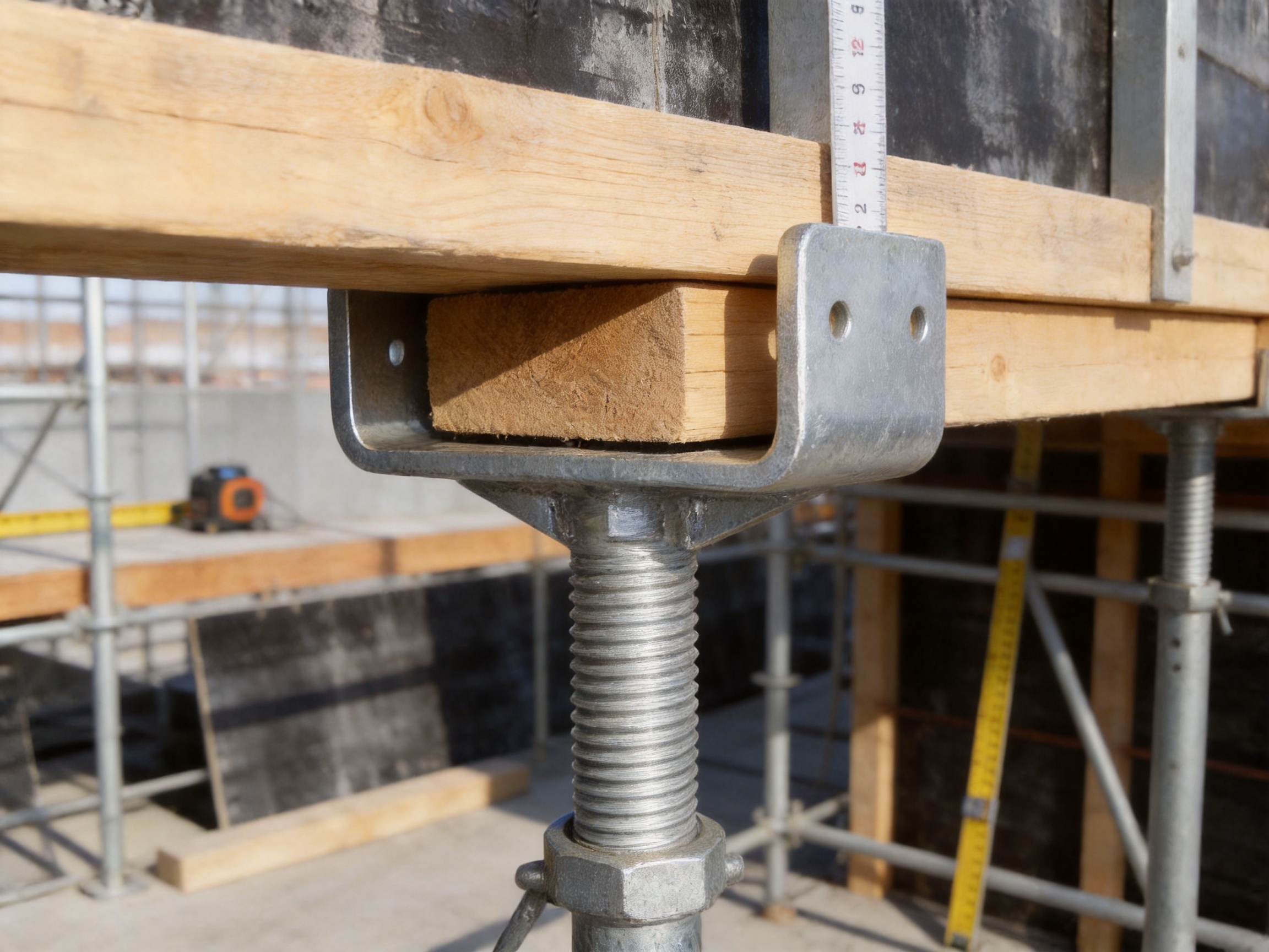
Unlike a conventional adjustable base, which is mainly used to level the bottom of a support structure, a U-head jack base is installed at the upper end of a supporting assembly. Its U-shaped head receives and supports the main beam, timber beam, steel beam, or other formwork member. Through a threaded adjustment mechanism, the operator can make fine corrections to the support elevation after the main support has been positioned. This top-adjustable configuration creates a direct and stable connection between the supporting system and the formwork.
The product is suitable for plane formwork, wall formwork, scaffolding platforms, precast component installation, and other temporary support applications. It can be connected with steel props, adjustable bases, ringlock or disc-lock scaffolding uprights, and coupler-type scaffolding systems. The standardized interface allows contractors to integrate the component into existing equipment without extensive modification or special adapters.
For contractors, rental companies, formwork specialists, infrastructure builders, and industrial fabricators, the U-head jack base offers a practical way to improve adjustment accuracy while simplifying installation. Its high-strength carbon steel construction, precision-manufactured threaded mechanism, hot-dip galvanized surface, and forged or stamped U-shaped head provide a durable solution for demanding construction environments.
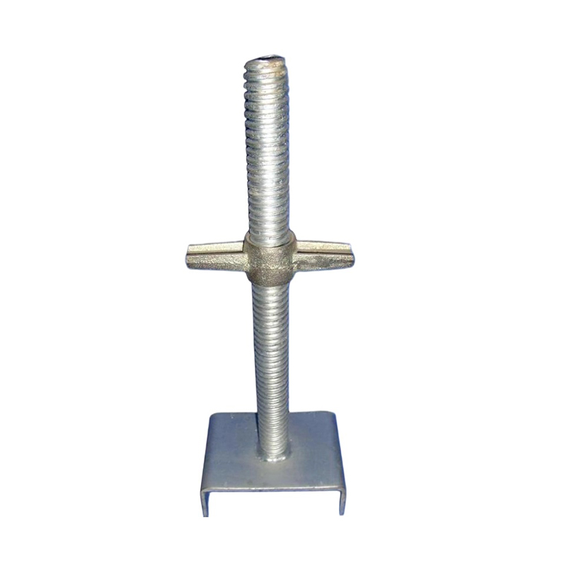
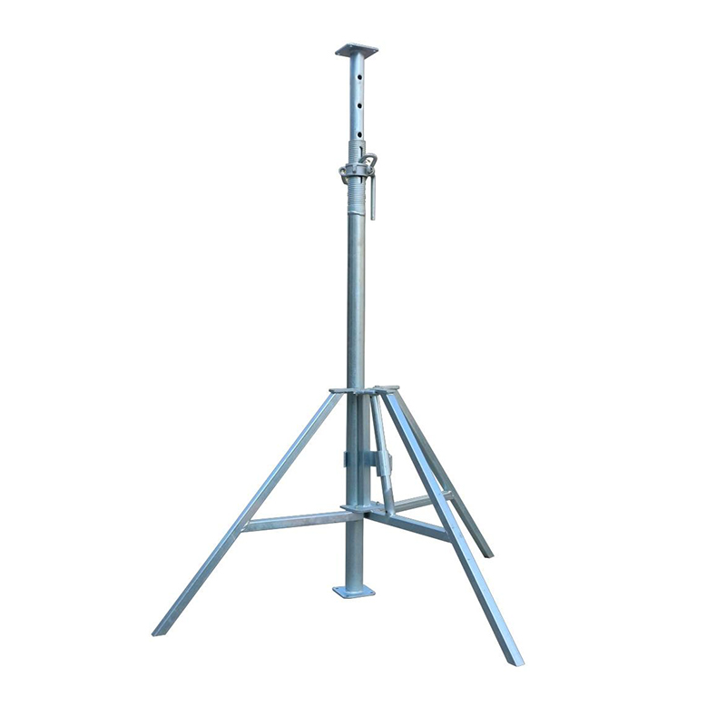
U-head Jack Base
What Is a U-Head Jack Base?
A U-head jack base is a top-adjustable load-bearing accessory used in temporary formwork and scaffolding support systems. The product normally consists of a U-shaped head, a vertical threaded stem, an adjustment nut or collar, and a rotating handle or operating feature. The bottom connection may be designed for compatibility with steel props, scaffold standards, base components, or other supporting members.
The U-shaped head creates a receiving channel for the formwork’s primary beam. Depending on the project, the channel may hold a timber beam, steel channel, rectangular section, or another structural member used to carry the formwork panels. The shape of the head helps prevent lateral movement and reduces the likelihood that the beam will slide out of position during installation or concrete placement.
The threaded stem provides vertical adjustment. Once the support tower, prop, or scaffold upright is erected, the worker rotates the adjustment mechanism to raise or lower the U-head. This allows the formwork elevation to be corrected without dismantling the main support structure. The adjustment is especially useful when the ground, supporting slab, scaffold base, or structural interface is not perfectly level.
In practical use, the product performs three connected functions. First, it supports the formwork beam. Second, it transfers the load from the beam into the lower support system. Third, it enables controlled adjustment of the formwork elevation. These functions make the U-head jack base more than a simple steel fitting. It is a load-transfer and alignment component that contributes directly to formwork accuracy and construction safety.
Why Top Adjustment Matters in Formwork Construction
Formwork systems are often assembled over large floor areas or along tall walls. Even when the main support components are manufactured accurately, field conditions can create height differences. Uneven ground, construction tolerances, slab irregularities, settlement, component wear, and variations in beam dimensions may all affect the final formwork position.
A bottom adjustable base can compensate for some of these differences before the support system is erected. However, it cannot always provide the final correction needed at the contact point between the support and the formwork beam. A top-adjustable U-head jack provides this final control directly below the load-bearing beam. This location makes adjustment more efficient because the worker can correct the formwork elevation at the point where the load is received.
Top adjustment is also useful when a large formwork area must be leveled progressively. Workers can install the primary support system, place the beams, check the elevation with measuring equipment, and then adjust individual U-head jacks as necessary. This approach reduces the need to remove and reposition complete support frames.
For wall formwork, the U-head jack base can be used to adjust upper support points and help maintain wall verticality. If the upper support is too high or too low, the formwork may tilt, resulting in dimensional errors after concrete placement. Controlled top adjustment helps compensate for these differences before the pour begins.
Main Structural Features
Integrated U-Shaped Support Head
The most visible feature is the U-shaped head. Its groove is designed to receive the formwork’s main beam and maintain a stable contact relationship between the beam and the support. Compared with a flat plate, a U-shaped head provides better lateral restraint and a larger degree of mechanical engagement.
The channel geometry helps keep the beam centered and reduces the risk of sliding or displacement during assembly. It also increases the effective contact area between the support head and the beam. A larger contact area can improve load distribution and reduce concentrated stress at a single edge or point.
The head can be manufactured in different dimensions to match project requirements. Customization may include the internal width, depth, steel thickness, connection dimensions, surface treatment, and overall height. This flexibility allows the product to accommodate different beam sizes and formwork configurations.
Precision Threaded Adjustment Mechanism
The threaded adjustment system is the main reason the product can provide precise elevation control. A fine-thread configuration enables smooth rotation and controlled vertical movement. According to the supplied product specifications, the adjustment accuracy can reach approximately plus or minus 0.5 millimeters, with an adjustment range of 30 to 150 millimeters.
The actual adjustment range and operating load should always be confirmed against the approved design, product drawing, and project conditions. Nevertheless, the combination of a fine thread and a practical adjustment range gives workers sufficient control for correcting common construction tolerances.
A well-manufactured thread must maintain consistent engagement under load. Poor thread quality can cause binding, excessive play, accelerated wear, or unreliable locking. Precision machining and quality inspection are therefore important parts of the manufacturing process. The thread, nut, stem, and bearing surfaces must work together so that adjustment remains smooth while the support is loaded within its specified capacity.
High-Strength Carbon Steel Construction
The product can be manufactured from Q235 or Q345 carbon steel, depending on the required design and application. These materials provide a useful combination of strength, weldability, formability, and availability. The U-shaped head may be formed through stamping, pressing, forging, or a combination of forming processes, while the threaded components are produced through controlled machining or rolling processes.
The steel grade alone does not determine the performance of the finished component. Head geometry, weld quality, thread engagement, dimensional accuracy, surface condition, and inspection procedures all influence load-bearing behavior. A professional manufacturing process must therefore control both raw material quality and production consistency.
Rotating Handle for Field Adjustment
The rotating handle allows workers to adjust the height without relying on complex tools. This is beneficial on busy construction sites where speed and accessibility are important. The handle can be operated from a practical position while the worker checks the formwork level and makes gradual corrections.
Tool-free or low-tool adjustment also reduces the number of accessories that must be carried around the work area. However, ease of operation does not remove the need for proper installation. The support must remain plumb, the adjustment must stay within the permitted range, and the final assembly must be checked before concrete placement.
Protective Surface Treatment
Construction environments frequently expose steel components to rain, cement slurry, moisture, dust, and repeated handling. Hot-dip galvanizing provides a protective zinc coating that helps prevent corrosion. The supplied specification identifies a coating thickness of at least 75 micrometers for the galvanized surface.
A galvanized finish can extend service life and reduce maintenance requirements, particularly for components used repeatedly by formwork rental companies. It also improves storage durability when products are kept outdoors or in partially protected yards. The threaded area should be manufactured and treated in a way that preserves smooth operation while maintaining corrosion resistance.
| Feature | Typical Product Characteristic | Practical Construction Benefit |
|---|---|---|
| U-shaped head | Grooved support for primary formwork beams | Improves beam positioning and reduces lateral movement |
| Fine-thread adjustment | Approximate adjustment accuracy of ±0.5 mm | Supports accurate level and verticality correction |
| Adjustment range | Approximately 30–150 mm, subject to design | Compensates for common field height deviations |
| Material options | Q235 or Q345 carbon steel | Provides strength, weldability, and fabrication flexibility |
| Load capacity | Approximately 80–120 kN per support, subject to verification | Supports formwork and concrete loads within approved limits |
| Surface protection | Hot-dip galvanized coating, specified at ≥75 μm | Improves resistance to moisture and construction corrosion |
| Operating handle | Rotating adjustment handle | Enables efficient field adjustment with minimal tooling |
| Interface compatibility | Steel props, scaffold uprights, and related systems | Reduces the need for project-specific adapters |
Advantages Compared with Conventional Support Accessories
More Than a Ground-Leveling Base
A conventional adjustable base is primarily installed at the bottom of a prop or scaffold standard. Its main purpose is to distribute the load onto the ground or supporting slab and to compensate for unevenness at the base. It remains an important component, but it does not directly retain the upper formwork beam.
The U-head jack base addresses a different part of the support system. It is positioned at the top and creates a shaped connection with the formwork beam. When used together, the adjustable base and U-head jack base provide adjustment at both ends of the support assembly. This arrangement allows the contractor to correct base conditions and upper formwork elevation independently.
More Secure Than a Flat Support Plate
A flat plate may provide a simple bearing surface, but it does not necessarily prevent a beam from moving sideways. The U-shaped head creates a physical boundary around the beam. This can improve stability during installation and concrete pouring, especially where vibration, worker movement, or accidental contact could otherwise disturb the beam.
The U-head is not a substitute for complete bracing, tie systems, or approved formwork design. Its benefit is that it improves the beam-to-support interface as part of a properly engineered assembly.
Finer Control Than Coarse Adjustment Systems
Some support products use coarse holes, pins, or limited adjustment positions. These arrangements may be adequate for approximate height setting, but they can make final leveling difficult. A threaded U-head jack allows continuous adjustment within its rated range. Workers can make small corrections instead of choosing between adjustment positions that are either too high or too low.
Fine adjustment is particularly valuable on large slabs, bridge decks, tunnel structures, and wall formwork where small differences can accumulate over long distances. Better control at the support points can reduce the time required for corrective work and help improve the quality of the finished concrete surface.
Better Load Distribution Than a Narrow Contact Point
The U-shaped head supports the beam along a defined channel rather than relying on a small contact point. This configuration can help distribute vertical forces and reduce localized pressure on the beam. It also helps maintain the intended load path from the formwork to the support system.
The component must still be selected and installed according to the calculated design load. The stated load range of 80 to 120 kN per support is a product reference and should not be treated as a universal allowable load for every arrangement. Spacing, eccentricity, unsupported length, thread extension, bracing, steel grade, and site conditions all affect the safe capacity of the completed system.
Greater Compatibility with Existing Equipment
Many contractors use several support systems on the same project. Steel props may be used in one area, disc-lock scaffolding in another, and coupler-type scaffolding in a third. A standardized U-head jack base can be configured to connect with different support members, helping contractors avoid purchasing a completely separate upper support solution for every system.
This compatibility can simplify inventory management. Rental companies may also benefit because a durable, adaptable accessory can be supplied with different support packages. Where a custom interface is required, the manufacturer can review the support dimensions, load requirements, and connection details before production.
Manufacturing Process and Quality Strengths
The performance of a U-head jack base depends heavily on manufacturing discipline. The component may appear simple, but it contains several critical areas: the U-shaped head, the stem, the thread, the adjustment nut, the handle, the welds, and the protective coating. Each part must meet dimensional and functional requirements.
Engineering Review and Product Configuration
Production begins with the review of the customer’s technical requirements. These may include head width, groove depth, adjustment range, stem diameter, connection type, required load, steel grade, coating, packaging, and applicable standards. For OEM orders, the supplier may prepare or review drawings, confirm tolerances, and identify any interference between the U-head and the proposed formwork beam.
Engineering review is especially important where the product will be integrated with a non-standard steel prop or a proprietary formwork system. The manufacturer should verify the interface rather than assuming that visually similar parts are interchangeable.
Raw Material Control
High-quality raw material supports consistent production. Steel plates, bars, tubes, and forgings should be checked for grade, thickness, surface condition, and traceability. Material certificates may be requested for projects requiring formal documentation.
Q235 steel is commonly selected for applications requiring reliable general-purpose structural performance and good weldability. Q345 provides higher strength and may be selected for more demanding load requirements, subject to design review. The appropriate material should be determined by the product drawing and engineering calculation rather than by grade selection alone.
Laser Cutting and Precision Plate Processing
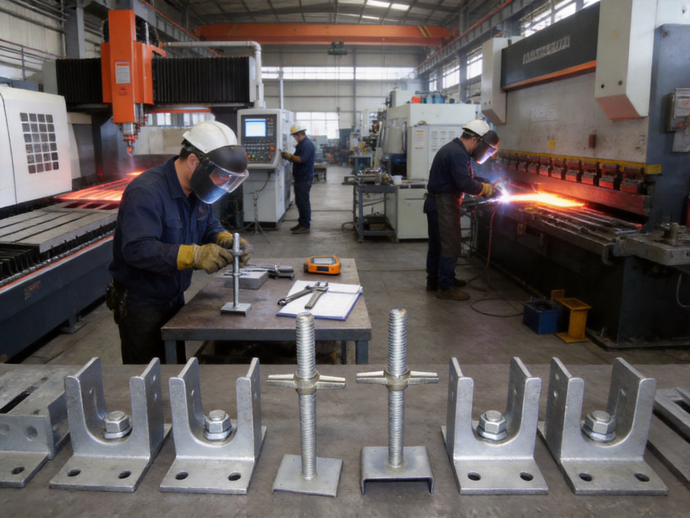
Advanced laser cutting equipment can be used to process steel plates and component blanks with accurate profiles. Laser cutting helps maintain repeatability in the U-head side plates, reinforcement plates, handle components, and other customized parts. It can also reduce manual marking errors and improve the consistency of hole positions and external dimensions.
For OEM production, CNC laser cutting is valuable because it allows the manufacturer to produce different product configurations efficiently. Digital drawings can be translated into controlled cutting programs, helping reduce variation between batches. After cutting, parts may be deburred, inspected, and prepared for bending, forming, or welding.
Bending, Stamping, and Forming
The U-shaped head must maintain its geometry under load. Depending on the design, the steel may be bent in a press brake, stamped in a forming die, forged, or produced through a multi-stage process. Controlled forming helps maintain the groove width, side-wall angle, radius, and alignment of the head.
Excessive deformation, inconsistent forming, or sharp stress concentrations can affect performance. For this reason, the manufacturing process should control forming parameters and inspect the finished head against the approved dimensions. Reinforcement plates or gussets may be added when required by the engineering design.
Thread Manufacturing and Inspection
The threaded stem and adjustment nut require careful manufacturing. Threads may be formed by rolling or produced through machining, depending on the design and size. Thread rolling can provide a strong, consistent profile and may improve surface durability, while machining offers flexibility for customized dimensions.
Inspection should verify thread pitch, diameter, engagement length, smooth rotation, and fit between mating components. The nut should travel along the stem without excessive looseness or binding. If the thread is damaged during welding, coating, or handling, the adjustment may become unreliable. Thread protection and post-treatment inspection are therefore essential.
Welding under Controlled Procedures
Welding connects the U-head, stem, reinforcement plates, and other components. The company’s manufacturing capabilities include certified AWS and EN welding craftsmanship. Applying recognized welding procedures helps ensure that welders, materials, joint preparation, and inspection methods are controlled.
Important welding considerations include joint design, pre-cleaning, heat input, weld size, penetration, distortion control, and visual appearance. Where required by project specifications, welds may be examined through additional non-destructive testing methods. A professional production line should also manage welding sequence to reduce distortion and maintain the alignment of the head with the threaded stem.
Surface Treatment
After fabrication and inspection, the component may receive hot-dip galvanizing. Before galvanizing, oil, scale, rust, and other contaminants must be removed so that the zinc coating can bond properly to the steel. Drainage and venting considerations are important for hollow or enclosed sections.
After galvanizing, the product should be checked for coating continuity, excessive buildup, blocked threads, sharp zinc projections, and dimensional changes that could affect assembly. Threaded parts may require appropriate post-treatment cleaning or protection to preserve smooth operation.
Final Assembly and Functional Testing
Final assembly includes fitting the threaded stem, nut, handle, and U-head components. The product should be rotated through its adjustment range to confirm that the mechanism operates correctly. The head should be checked for alignment, and the support should be examined for visible cracks, deformation, incomplete welds, or coating defects.
For products supplied to major infrastructure projects, inspection records can include material certificates, dimensional reports, weld inspection results, coating measurements, load test information, and batch identification. Such records improve traceability and make it easier for the customer to manage quality documentation.
Load-Bearing Performance and Design Considerations
The U-head jack base is intended to carry substantial vertical loads, including the weight of formwork, reinforcement, fresh concrete, workers, tools, equipment, and construction effects. The stated product range is approximately 80 to 120 kN per support. The actual allowable capacity must be confirmed for the specific model and installation condition.
Load capacity is influenced by several factors. The first is the material strength and cross-sectional geometry of the stem and head. The second is the effective thread engagement and the amount of extension. The third is the stability of the lower support system. The fourth is the position of the beam within the U-head. The fifth is the presence or absence of horizontal bracing and restraint.
A support should be loaded as centrally as possible. Eccentric loading can create bending moments in the stem or localized pressure on the head. The U-shaped groove should match the beam dimensions so that the beam is properly seated rather than resting on a corner or unstable edge.
The adjustment should remain within the manufacturer’s recommended working range. Excessive extension can reduce stiffness and increase the risk of buckling or instability. The support system should also be erected on a firm, level, and adequately designed base. A strong U-head cannot compensate for inadequate ground bearing or poor lower support stability.
Before pouring concrete, the entire formwork system should be checked for plumbness, levelness, bracing, connections, support spacing, and signs of movement. The U-head jack base contributes to this system but does not replace engineering design, inspection, or safe construction procedures.
Applications in Different Construction Scenarios
Plane Formwork Support
In slab and floor formwork, U-head jack bases are installed at the top of steel props, scaffold standards, or temporary support towers. The U-shaped head receives the primary beam, while secondary beams and formwork panels are placed above it. Workers can adjust the U-head to establish the required elevation and compensate for differences in the supporting surface.
This application is useful for concrete floors, elevated slabs, bridge decks, industrial platforms, and large horizontal pours. The product helps maintain a consistent support interface across a broad area. When combined with a suitable layout and regular surveying, it can contribute to a flatter and more uniform formwork surface.
Wall Formwork Support
Wall formwork must remain vertical and stable against pressure from fresh concrete. The upper support location is important because small deviations can cause the wall panels to tilt. A U-head jack base can be used as a top adjustment component to correct the height and position of the supporting beam.
It may be used with wall formwork frames, steel supports, inclined braces, or temporary access and support systems, depending on the project design. The product helps workers make controlled corrections before pouring, reducing the risk of uneven wall dimensions and excessive finishing work.
Ringlock and Disc-Lock Scaffolding
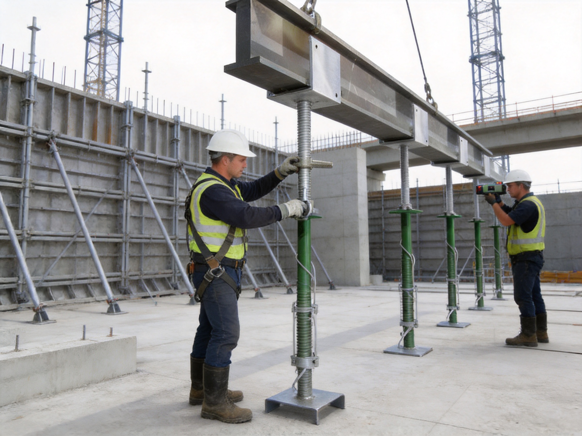
Ringlock and disc-lock scaffolding systems are widely used for temporary access, shoring, and formwork support. A U-head jack base can be installed at the upper end of a scaffold standard when the system is designed to carry formwork beams or related temporary loads.
The product provides a top adjustment function that complements the modular height increments of the scaffold. Instead of relying only on standard ledger and transom levels, the contractor can make final corrections through the threaded head. Connection dimensions and load requirements must be confirmed to ensure compatibility with the specific scaffold system.
Coupler-Type Scaffolding
In coupler-type scaffolding, support frames are assembled from tubes and fittings. A U-head jack base can be integrated with the top of the support arrangement when the connection is properly designed and secured. It provides a practical way to support beams while retaining the flexibility of a tube-and-coupler structure.
Because coupler systems can vary significantly in configuration, the manufacturer should review the tube diameter, connection method, expected load, and required adjustment. The product should not be attached through improvised methods that may compromise the load path.
Precast Component Installation
Precast wall panels, floor slabs, beams, and other components may require temporary support during installation. A U-head jack base can help adjust the elevation or vertical position of a precast element before permanent connections are completed.
The U-shaped head can provide a stable receiving point for temporary support members. Fine adjustment is useful when aligning precast components with adjacent elements, embedded plates, openings, or connection details. The temporary support must be designed for the component weight and installation loads, and it must remain in place until the permanent structure is capable of carrying the load.
Bridge, Tunnel, and Infrastructure Projects
Large infrastructure projects often involve irregular geometry, demanding schedules, repeated formwork cycles, and strict quality requirements. The U-head jack base can be used in bridge deck formwork, pier and abutment formwork, tunnel lining support, culvert construction, and other temporary works.
Its value in these projects comes from repeatable adjustment and durable construction. When many support points must be set to a common elevation, a consistent threaded mechanism can reduce manual correction time. The galvanized finish is also useful where components are exposed to moisture, cement dust, and outdoor storage conditions.
OEM Customization and Project-Specific Solutions
Standard U-head jack bases are suitable for many common support arrangements, but projects may require customized dimensions or interfaces. OEM manufacturing allows the product to be adapted to the customer’s formwork beam, support system, load requirement, and installation method.
Customization may include the width and depth of the U-shaped groove, the length and diameter of the threaded stem, the adjustment range, the base connection, the handle configuration, the steel grade, the surface treatment, and the marking method. The product can also be supplied in different packaging formats for container transport, warehouse handling, or project-site distribution.
A suitable customization process begins with technical information. Customers should provide drawings or photographs of the existing support system, beam dimensions, required working load, expected adjustment range, installation environment, and applicable standards. The manufacturer can then review the design and recommend a practical configuration.
For large orders, sample production can be used to confirm fit and operation before mass manufacturing. Dimensional checks should verify that the U-head receives the beam correctly and that the lower connection matches the support standard. Functional testing should confirm that the threaded mechanism operates smoothly under the intended conditions.
OEM production is especially valuable for contractors that operate proprietary formwork systems or need to replace imported accessories. Instead of modifying the entire support arrangement, the customer can obtain a component designed around the existing equipment. This can reduce adaptation work and make the product easier for site workers to adopt.
Manufacturing Capability for Heavy Steel Components
The manufacturer behind this product specializes in steel formwork, ringlock scaffolding, heavy-duty steel structures, and OEM metal fabrication. Its equipment and production capabilities include laser cutting, steel plate processing, bending, forming, welding, assembly, and surface treatment coordination.
This broader manufacturing background is important because a U-head jack base must be produced as an engineered steel component rather than as an isolated hardware item. Experience with large formwork and scaffolding systems helps the manufacturer understand load transfer, field installation, component compatibility, and the practical requirements of construction contractors.
The company applies automated processing and standardized production lines to improve repeatability. It also reports compliance with ISO 9001 and experience with BS1139 and EN74-related scaffolding requirements. These standards and quality systems provide a framework for process control, inspection, documentation, and product consistency.
Its welding capabilities include AWS and EN practices, supporting the production of welded steel components for construction and infrastructure applications. The company also holds multiple utility patents and has supplied components for major bridge, transport, energy, and industrial projects. This project experience contributes to an understanding of strict manufacturing requirements and the importance of stable batch quality.
For global customers, an integrated supplier can provide more than one accessory. The same production partner may manufacture formwork panels, steel props, scaffolding components, structural frames, laser-cut plates, and customized heavy steel assemblies. This can simplify procurement and help maintain interface consistency across a project.
Quality Control from Material to Shipment
Quality control should cover the complete production chain rather than only the final appearance. For a U-head jack base, the following control points are particularly important.
Dimensional Inspection
Inspectors should measure the groove width, groove depth, head alignment, stem diameter, thread dimensions, adjustment range, connection size, and overall height. Dimensional records help confirm that the product matches the approved drawing and can be connected to the customer’s support system.
Weld Inspection
Welds should be checked for continuity, correct size, surface defects, undercut, porosity, cracks, and distortion. The inspection method should follow the project requirement and the applicable welding procedure. Where necessary, additional non-destructive testing can be applied to critical joints.
Thread and Operation Testing
The adjustment nut should rotate smoothly over the required threaded length. The mechanism should not show excessive clearance, jamming, or damage. Operators should also confirm that the handle is securely connected and can transmit sufficient turning force.
Coating Inspection
The galvanized coating should be continuous and sufficiently bonded to the steel. Coating thickness can be checked with an appropriate gauge, with the supplied specification identifying a target of at least 75 micrometers. Threads and connection areas should be examined to ensure that coating buildup does not prevent proper assembly.
Load and Functional Verification
Where required, representative samples or production batches may undergo load testing. The test should be based on the approved design and should observe deformation, thread behavior, head stability, and any signs of failure. Testing should not be interpreted as permission to exceed the specified working load in the field.
Packaging and Traceability
Products should be protected against impact, moisture, and thread damage during transportation. Suitable packaging can include bundled steel frames, protective separators, cartons for smaller parts, or customized export packing. Batch markings, inspection records, and packing lists make it easier to identify products during receiving and installation.
Installation and Safe Use Guidelines
Before installation, workers should confirm that the U-head jack base is the correct model and that it has no visible cracks, severe corrosion, bent parts, damaged threads, or missing components. The supporting structure should be assembled according to the approved formwork or scaffolding layout.
The lower support must stand on a firm and adequately sized base. If an adjustable base is used, it should be correctly positioned and secured. The support standard or prop should remain vertical, and the U-head should be aligned with the formwork beam.
The formwork beam should be fully seated within the U-shaped groove. It should not rest on an unstable corner, partial edge, or obstruction. The worker should operate the threaded adjustment gradually and avoid sudden force that could damage the thread or disturb the support.
After the desired elevation is reached, the adjustment mechanism should be secured according to the product design. The complete system should then be checked for level, verticality, spacing, bracing, connection tightness, and signs of instability. Any gap or unexpected movement should be corrected before loading.
During concrete placement, the formwork should be observed for movement, excessive deflection, unusual noise, or local settlement. If a problem is detected, the pour should be managed according to the project safety procedure. Workers should never attempt unsafe adjustment beneath a heavily loaded or unstable formwork system.
After use, the component should be cleaned of concrete residue and inspected before storage. Threads should be protected if recommended by the manufacturer. Damaged or permanently deformed components should be removed from service and evaluated by a qualified person.
Efficiency Benefits on the Construction Site
The U-head jack base can improve construction efficiency in several ways. Its integrated top support reduces the number of separate connection pieces required at the beam interface. The rotating handle allows quick adjustment, and the threaded mechanism enables workers to make small corrections without dismantling the complete support system.
Improved adjustment accuracy can also reduce rework. If the formwork is not level before concrete placement, workers may need to remove panels, reposition beams, or correct finished concrete surfaces. A precise top-adjustable accessory gives the team greater control during the preparation stage.
The product can support faster formwork cycles. When a contractor repeats the same formwork arrangement across multiple floors, bridge sections, or wall segments, standardized U-head jack bases can be reused. Consistent dimensions and operation make it easier for workers to become familiar with the installation sequence.
Durability is another efficiency factor. A galvanized component with a robust steel head can withstand repeated handling and exposure better than an inadequately protected product. Longer service life reduces replacement frequency and helps rental companies maintain a reliable inventory.
Selection Guide for Buyers and Contractors
When selecting a U-head jack base, buyers should consider the intended formwork beam dimensions first. The internal groove must provide a secure fit without excessive clearance. The beam should be supported over a stable area, and the head should not create an unintended point load.
The required load should then be determined from the temporary works design. Buyers should request the rated capacity, test basis, material information, and recommended adjustment range. If the project involves high loads, large spans, or unusual geometry, the component should be reviewed by the project engineer.
Connection compatibility is also critical. The stem, base, socket, or other interface must fit the selected steel prop or scaffold upright. Customers should not rely only on nominal sizes because different manufacturers may use different thread forms, diameters, and connection details.
Environmental conditions should guide surface treatment. Hot-dip galvanizing is suitable for many outdoor and humid construction settings. Projects exposed to aggressive chemicals, coastal conditions, or special industrial atmospheres may require additional review of the coating system and maintenance plan.
Finally, buyers should evaluate the supplier’s manufacturing capability. A supplier with laser cutting, controlled forming, certified welding, inspection systems, and experience in heavy steel components is better positioned to deliver consistent OEM products than a supplier focused only on basic hardware trading.
Frequently Asked Questions
What is the primary purpose of a U-head jack base?
Its primary purpose is to support a formwork beam at the top of a temporary support system while allowing precise vertical adjustment. It improves the connection between the support and the formwork and helps compensate for construction height deviations.
How is a U-head jack base different from an adjustable base?
An adjustable base is generally installed at the bottom of a prop or scaffold standard to level the support and distribute load onto the ground or supporting slab. A U-head jack base is installed at the top and supports the formwork beam. The two products can be used together to provide adjustment at both ends of the support assembly.
What materials are available?
The supplied product information identifies Q235 and Q345 high-strength carbon steel as material options. The correct grade depends on the design, required capacity, component geometry, and customer specification.
What is the adjustment range?
The stated adjustment range is approximately 30 to 150 millimeters, with an indicated adjustment accuracy of about plus or minus 0.5 millimeters. The final range should be confirmed for the selected model and approved drawing.
How much load can one U-head jack base support?
The supplied product information indicates a capacity range of approximately 80 to 120 kilonewtons per support. The actual allowable working load must be verified for the specific product and complete support arrangement. Thread extension, eccentric loading, bracing, spacing, and foundation conditions all affect safe performance.
Can it be used with ringlock or disc-lock scaffolding?
Yes, it is designed to be adaptable to support components such as disc-lock scaffolding uprights and other standardized systems. The exact interface, dimensions, and project load must be confirmed before use.
Can the product be customized?
Yes. OEM customization may include U-head dimensions, stem length, thread size, adjustment range, connection interface, material, handle design, surface treatment, marking, and packaging. Technical drawings and application details should be reviewed before production.
Is hot-dip galvanizing necessary?
Hot-dip galvanizing is not required for every indoor or short-term application, but it is highly beneficial for outdoor, humid, and repeatedly reused construction equipment. The supplied specification identifies a galvanized coating thickness of at least 75 micrometers.
Can workers adjust the product under full load?
Adjustment under load should only be performed when specifically permitted by the approved design and safe work procedure. In general, workers should establish the required elevation before loading and should never attempt adjustment beneath unstable or dangerously loaded formwork.
What should be checked before concrete pouring?
The team should check the support layout, base condition, verticality, U-head seating, beam alignment, adjustment range, bracing, connections, formwork level, and signs of movement. The complete system should be approved according to the project’s temporary works inspection procedure.
How should used U-head jack bases be maintained?
After use, remove concrete residue, inspect the head and stem, clean and protect the thread, and store the product in a dry or suitably protected area. Components with cracks, severe corrosion, damaged threads, or permanent deformation should be removed from service.
Why choose a manufacturer with heavy steel fabrication capability?
A heavy steel fabricator can control laser cutting, bending, forming, welding, assembly, and inspection within an integrated production process. This is particularly useful for customized products and projects requiring reliable dimensions, traceability, and compatibility with larger formwork or scaffolding systems.
Conclusion
The U-head jack base is a focused solution for one of the most important interfaces in temporary formwork: the connection between the support structure and the formwork beam. Its U-shaped head improves beam retention and load distribution, while its precision threaded mechanism allows workers to make controlled height corrections. High-strength carbon steel construction, hot-dip galvanizing, standardized interfaces, and a practical rotating handle further improve its suitability for repeated construction use.
Compared with a basic adjustable base or flat support plate, the U-head jack base provides a more complete top-support function. It helps contractors address alignment, levelness, and connection stability at the location where these factors directly affect formwork performance. When correctly selected and installed, it can contribute to improved pouring accuracy, reduced rework, faster formwork cycles, and safer temporary works.
The product is also well suited to OEM manufacturing. Through laser cutting, precision steel processing, controlled forming, certified welding, surface treatment, inspection, and customized assembly, an experienced heavy steel manufacturer can adapt the U-head jack base to different beam sizes, support systems, load requirements, and project standards.
For contractors and engineering companies seeking a reliable formwork support accessory, the most important considerations are not only nominal dimensions or price. Product geometry, thread quality, load verification, interface compatibility, corrosion protection, manufacturing consistency, and technical support should all be evaluated. A well-designed and professionally manufactured U-head jack base can become a durable and valuable component in slab formwork, wall formwork, scaffolding support, precast installation, and major infrastructure construction.
References
1. International Organization for Standardization. ISO 9001, Quality Management Systems—Requirements.
2. European Committee for Standardization. EN 74, Couplers, Spigot Pins and Baseplates for Use in Falsework and Scaffolds.
3. British Standards Institution. BS 1139, Metal Scaffolding—Relevant Requirements for Tubes, Couplers, and Accessories.
4. American Welding Society. Structural Welding Code—Steel, AWS D1.1/D1.1M.
5. European Committee for Standardization. EN 1090, Execution of Steel Structures and Aluminium Structures.
6. International Organization for Standardization. ISO 1461, Hot Dip Galvanized Coatings on Fabricated Iron and Steel Articles—Specifications and Test Methods.
7. American Concrete Institute. Guide to Formwork for Concrete.
8. International Labour Organization. Safety and Health in Construction—Temporary Works and Construction Equipment Guidance.
9. Manufacturer-provided technical information for U-head jack bases, steel formwork systems, scaffolding accessories, and OEM heavy steel fabrication.
Product: U-head Jack Base


- Location
- Group 3, Fangzhuang Village, Rucheng Subdistrict, Rugao City, Nantong, Jiangsu, China
- Follow us
- Phone
- +86-13646196162
- info@hysonindustry.com
