 +86-13646196162
 info@hysonindustry.com




 русский
 عربى



U-Head Jack Base: Precision Support for Formwork and Scaffolding Systems
 2026.09.21
Content
- 1 What Is a U-Head Jack Base?
- 2 Why the U-Shaped Head Matters
- 3 Precision Height Adjustment
- 4 Load-Bearing Performance and Structural Reliability
- 5 Key Product Specifications
- 6 Advantages Over Conventional Support Accessories
- 7 Manufacturing Process
- 8 Quality Control and Engineering Capability
- 9 Compatibility with Formwork and Scaffolding Systems
- 10 Application Scenario: Plane Formwork Support
- 11 Application Scenario: Wall Formwork Support
- 12 Application Scenario: Scaffolding and Temporary Works
- 13 Application Scenario: Precast Component Installation
- 14 Installation and Operating Guidance
- 15 Maintenance and Reuse
- 16 Customization and OEM Services
- 17 Why Choose an Experienced Heavy Steel Manufacturer?
- 18 Comparison with Alternative Products
- 19 Safety Considerations
- 20 Inspection Checklist
- 21 Frequently Asked Questions
- 21.1 What is the main purpose of a U-head jack base?
- 21.2 Can a U-head jack base be used with steel props?
- 21.3 Can it be used with ringlock or disc-lock scaffolding?
- 21.4 What is the typical adjustment range?
- 21.5 How accurate is the height adjustment?
- 21.6 What materials are commonly used?
- 21.7 How much load can one U-head jack base support?
- 21.8 Is the product corrosion resistant?
- 21.9 Can the U-shaped head be customized?
- 21.10 Can the product support wall formwork?
- 21.11 Can it be used for precast components?
- 21.12 Does the U-head jack base replace bracing?
- 21.13 How should used components be maintained?
- 21.14 What information is needed for an OEM quotation?
- 22 Conclusion
- 23 References
- 24 Product: U-head Jack Base
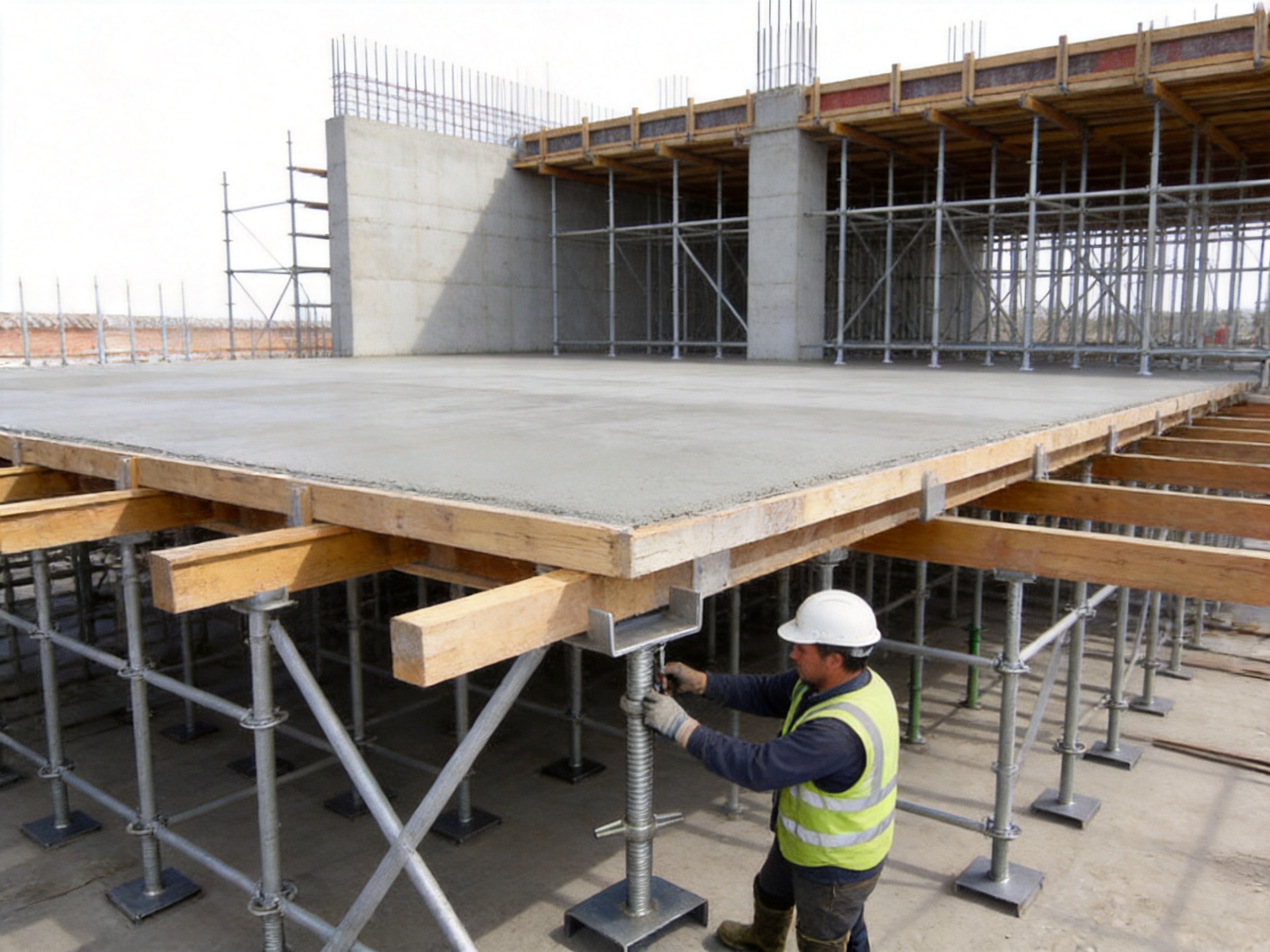
The U-head jack base is a critical load-bearing and adjustment component used in formwork support systems, scaffolding structures, temporary works, and precast construction. Designed to connect vertical support members with the underside of a formwork beam or structural member, it combines secure top support with accurate height adjustment. This combination makes it more than a conventional adjustable base. It is a specialized interface component that helps contractors achieve stable support, accurate elevation, even load transfer, and safer construction operations.
In modern construction, the performance of a support system depends not only on the strength of its vertical props or scaffolding standards, but also on the quality of the connection between the support and the formwork. A poorly fitted connection can create localized stress, beam movement, uneven concrete placement, and difficulties during leveling. The U-head jack base addresses these problems with a U-shaped top saddle, a precision threaded adjustment mechanism, and a robust steel body engineered for demanding site conditions.
Nantong Hyson Road And Bridge Formwork Co., Ltd. manufactures U-head jack bases and other steel construction products through integrated cutting, forming, welding, machining, galvanizing, inspection, and packaging processes. The company specializes in custom steel formwork, scaffolding, steel props, heavy steel structures, and OEM metal fabrication. Its manufacturing capabilities allow the U-head jack base to be supplied as a standard product or customized for specific support systems, beam dimensions, load requirements, and project conditions.
What Is a U-Head Jack Base?
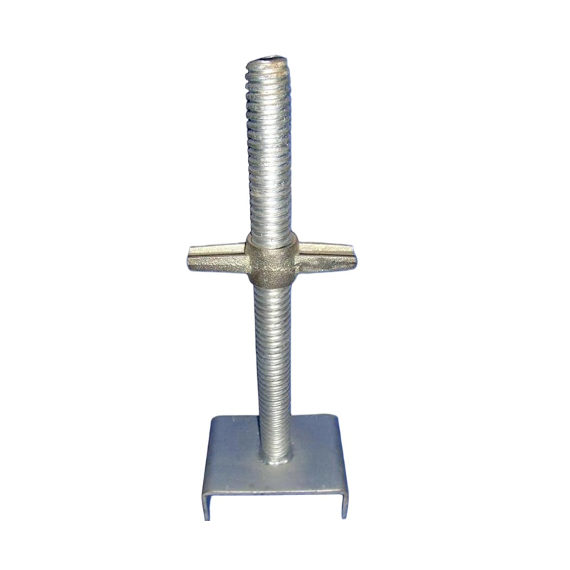
A U-head jack base is an adjustable top support accessory installed at the upper end of a steel prop, scaffolding upright, or other vertical support member. Its U-shaped head receives and supports a primary formwork beam, timber beam, steel channel, or similar structural element. The threaded jack mechanism allows workers to raise or lower the supported member by rotating the adjustment handle or collar.
The product has two primary functions. First, it creates a positive mechanical seat for the formwork beam. The U-shaped head helps prevent lateral movement and reduces the risk of the beam sliding from the support. Second, it provides controlled vertical adjustment. Workers can compensate for differences in floor elevation, support length, formwork tolerances, and construction requirements without dismantling the entire support assembly.
This design is especially useful where formwork must be leveled accurately before concrete placement. In slab construction, the U-head jack base can be used to adjust the elevation of primary beams supporting plywood panels or modular formwork. In wall formwork, it can assist with top support positioning and vertical alignment. In scaffolding applications, it can serve as an adjustable top component for work platforms, temporary structures, and support towers.
Unlike a flat adjustable base, which is mainly used to distribute the lower end of a support onto the ground or a base plate, the U-head jack base is designed to engage with the upper structural member. It therefore provides both load transfer and top-side positioning. This makes it an essential complement to adjustable bases, steel props, ringlock scaffolding, cuplock scaffolding, and other temporary support systems.
Why the U-Shaped Head Matters
The U-shaped head is the defining feature of this product. Its geometry creates a receiving channel that supports the underside of a beam over a broader contact area than a simple flat plate. By holding the beam within the saddle, the design reduces the possibility of lateral displacement during installation, concrete pouring, vibration, and routine movement around the work area.
A wider and better-fitted contact surface also helps distribute the supported load. When a beam rests on a narrow or uneven contact point, stress can concentrate in one area. This can lead to local deformation of the beam, damage to the formwork, or instability in the support arrangement. The U-shaped head reduces these risks by creating a more stable interface between the support and the formwork beam.
The U-head structure can be manufactured to suit different beam widths, support configurations, and project requirements. Standardized designs are suitable for widely used formwork and scaffolding systems, while customized versions can be produced for non-standard primary beams, special steel channels, prefabricated components, or unusual support layouts.
Another advantage is ease of installation. A worker can place the beam directly into the U-shaped saddle without needing to create a separate connection plate or temporary fastening arrangement. When the head is correctly positioned and the adjustment mechanism is tightened, the beam remains supported while the remaining formwork components are installed.
Precision Height Adjustment
Accurate elevation control is one of the most important requirements in formwork construction. Even a small height difference between adjacent supports can affect slab thickness, beam alignment, wall verticality, and the final appearance of a concrete structure. The U-head jack base provides a practical way to make fine adjustments during setup and before pouring.
The product uses a precision threaded mechanism with an adjustment range of approximately 30 millimeters to 150 millimeters, depending on the selected configuration. The adjustment accuracy can reach approximately plus or minus 0.5 millimeters under suitable operating conditions. This allows workers to correct support height differences without using improvised packing materials or repeatedly repositioning the entire support system.
The threaded adjustment principle is simple and reliable. When the handle or adjustment collar is rotated, the threaded component moves vertically in relation to the fixed support body. This transforms rotational movement into controlled linear movement. Because the thread provides mechanical resistance, the adjusted position can remain stable when the component is correctly loaded and secured.
Fine adjustment is especially useful on uneven floors, sloped work surfaces, large slab areas, and projects where support points are installed over different structural levels. It also helps compensate for manufacturing tolerances in beams, props, scaffolding standards, and formwork panels.
Precise adjustment can reduce the amount of corrective work required before concrete placement. It may also improve the flatness of floor slabs, the verticality of wall formwork, and the accuracy of precast component installation. By reducing uneven settlement and misalignment, the component supports more consistent construction quality.
Load-Bearing Performance and Structural Reliability
The U-head jack base is manufactured from high-strength carbon steel grades such as Q235 or Q345, according to the design and application. The material selection provides a balance of strength, weldability, formability, and cost efficiency. The U-shaped support section is formed through stamping and forging or other controlled forming processes, creating a strong component with good resistance to compression and deformation.
Depending on the model, design, and verified working conditions, a single U-head jack base can support a load in the approximate range of 80 kilonewtons to 120 kilonewtons. The exact safe working load must be confirmed according to the product drawing, support configuration, thread condition, eccentricity, installation method, and applicable engineering standards.
Load capacity is not determined by the head alone. The complete support system must be evaluated, including the vertical prop, threaded rod, nut, base plate, support spacing, beam arrangement, floor condition, and bracing. The U-head jack base is most effective when used as part of a properly designed and inspected support assembly.
The broad U-shaped seat helps reduce localized pressure on the formwork beam. The steel body provides resistance to compression, while the threaded adjustment section allows the height to be set without compromising the support position. When properly aligned, the vertical load is transferred through the jack body and into the supporting prop or scaffold standard.
For heavy-duty applications, the product can be specified with reinforced head plates, larger threaded rods, increased saddle width, special locking arrangements, or customized dimensions. These options make the U-head jack base suitable for a wide range of construction environments, including high-load slab formwork, bridge works, infrastructure projects, industrial buildings, and precast installation.
Key Product Specifications
| Item | Typical Description | Project Consideration |
|---|---|---|
| Product type | Adjustable U-head jack base | Installed at the top of a vertical support |
| Primary function | Beam support and height adjustment | Used for leveling and load transfer |
| Head design | U-shaped saddle | Supports beams and helps prevent movement |
| Common material | Q235 or Q345 carbon steel | Grade selected according to load and design |
| Adjustment range | Approximately 30 mm to 150 mm | Final range depends on the model |
| Adjustment accuracy | Approximately ±0.5 mm | Depends on thread condition and operation |
| Approximate load range | 80 kN to 120 kN per support | Must be verified for the complete system |
| Surface treatment | Hot-dip galvanizing | Typical coating thickness is at least 75 micrometers |
| Operating method | Rotating handle or adjustment collar | No specialized power tool is normally required |
| Compatible systems | Steel props, ringlock scaffolding, disc-lock systems, and formwork | Interface dimensions should be confirmed before ordering |
The specifications above represent typical product characteristics. Final dimensions, working loads, thread sizes, saddle width, coating requirements, and connection details should be confirmed through approved drawings and technical documentation before production or use.
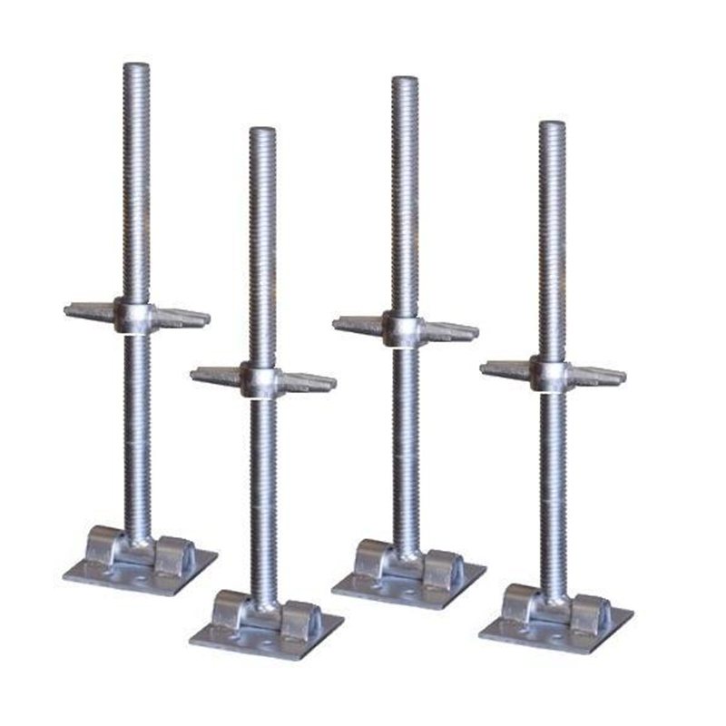
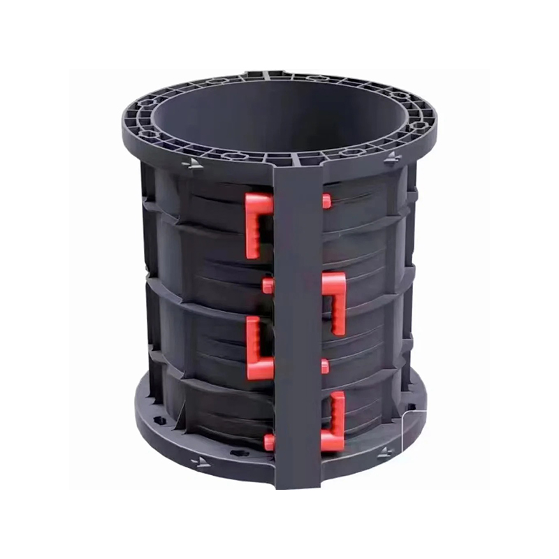
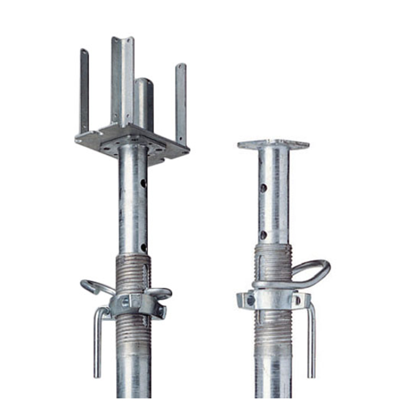
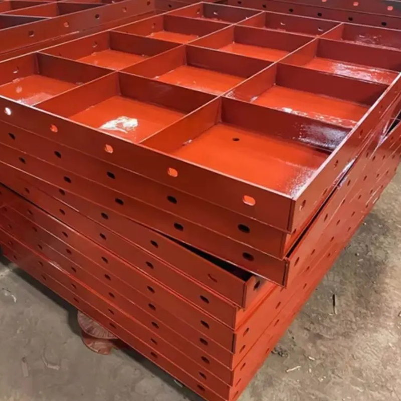
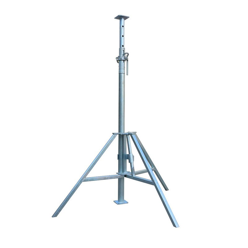
U-head Jack Base
Advantages Over Conventional Support Accessories
More Secure Than a Flat Top Plate
A flat top plate can support a beam, but it may provide limited resistance against lateral movement. When workers move across the formwork or when concrete is placed and vibrated, the beam may shift if it is not otherwise restrained. The U-shaped head creates a physical receiving channel that improves positioning and provides a more secure connection.
More Precise Than Improvised Packing
Some construction teams use timber wedges, loose steel plates, or other packing materials to correct support height. These methods can be inconsistent and may introduce gaps, compression, or local instability. The threaded adjustment mechanism of the U-head jack base provides a controlled alternative. Height changes can be made gradually and measured more reliably.
More Versatile Than Fixed-Length Supports
Fixed-length steel supports are strong but do not provide convenient adjustment. If the support height does not match the project requirement, workers may need to change the prop, alter the base arrangement, or use additional packing. The adjustable U-head design accommodates a range of site conditions and reduces the need for multiple fixed-length components.
More Adaptable Than Application-Specific Connectors
Some support connectors are designed for only one formwork model or one type of scaffold. A standardized U-head jack base can work with various beams, props, and scaffolding uprights. This adaptability simplifies inventory management and allows contractors to use the same component across different projects.
More Durable in Difficult Environments
Hot-dip galvanizing protects the steel surface against moisture and corrosion. This is important on outdoor construction sites, in humid climates, near coastal areas, and in projects where components are stored or used repeatedly. The galvanized coating also supports longer service life when the product is cleaned, inspected, and handled correctly.
Manufacturing Process
The performance of an adjustable support component depends heavily on manufacturing accuracy. Thread quality, head alignment, steel thickness, weld integrity, dimensional consistency, and surface treatment all influence the final product. Nantong Hyson Road And Bridge Formwork Co., Ltd. applies an integrated manufacturing process for steel construction components, from material preparation through final inspection and packaging.
Material Selection and Incoming Inspection
Production begins with the selection of appropriate carbon steel material. Q235 and Q345 grades may be used according to the required design strength and forming requirements. Incoming material is checked for dimensions, surface condition, chemical identification where required, and conformity with purchasing specifications.
Proper material control is important because the U-shaped head and threaded components must withstand repeated loading and adjustment. Material with excessive surface defects, inconsistent thickness, or uncertain grade can affect forming accuracy and long-term reliability. Controlled sourcing and inspection help establish a stable manufacturing foundation.
Laser Cutting and Plate Preparation
Advanced laser cutting equipment is used to process steel plates and other components with high dimensional accuracy. Laser cutting can produce clean edges, repeatable profiles, and complex shapes required for head plates, reinforcing parts, base plates, brackets, and custom accessories.
Compared with less controlled cutting methods, CNC laser processing can reduce dimensional variation and minimize the amount of secondary finishing. Accurate cutting also supports better fit-up during forming and welding. For OEM orders, digital drawings can be translated into repeatable cutting programs, helping maintain consistency across large production batches.
Laser cutting is also useful for customized U-head jack bases. A customer may require a specific saddle width, plate thickness, mounting hole, connection shape, or reinforcement detail. The cutting process can accommodate such variations without requiring extensive changes to the production line.
Forming, Stamping, and Forging
The U-shaped head must maintain its geometry under compression. Controlled stamping, bending, or forging processes are used to form the saddle and related steel parts. Process parameters are selected according to material thickness, radius, shape, and required mechanical performance.
Accurate forming is essential because an incorrectly shaped saddle may not provide full contact with the beam. Excessive distortion can also affect alignment between the head and the threaded support. Production tooling and fixtures help control the shape of the U-head during forming and ensure repeatable dimensions.
For high-load designs, the head may include reinforcement plates, thicker side walls, or forged sections. These details increase resistance to deformation and improve load transfer. The final configuration is selected according to the intended support system and customer requirements.
Threaded Component Manufacturing
The adjustment screw, nut, collar, or threaded rod is a key part of the product. Thread accuracy affects adjustment smoothness, holding ability, and service life. Threads are produced and inspected using controlled machining or rolling processes suitable for the selected diameter and design.
Before assembly, threaded parts should be checked for pitch consistency, surface damage, burrs, and proper engagement. The adjustment mechanism must rotate smoothly without excessive looseness. A clean and correctly formed thread also makes it easier for workers to adjust the height on site.
Welding and Assembly
Where welded construction is used, the U-shaped head, threaded sleeve, base plate, reinforcement parts, and other components are assembled using controlled fixtures. Proper fit-up helps maintain perpendicularity and reduces distortion during welding.
Nantong Hyson Road And Bridge Formwork Co., Ltd. applies certified welding craftsmanship based on AWS and EN practices. Welding personnel, equipment, consumables, and procedures can be managed according to the requirements of the project. Welds are inspected for appearance, continuity, dimensional accuracy, and other specified quality criteria.
For critical or customized orders, additional non-destructive testing or project-specific inspection can be arranged when required by the customer or applicable specification. Quality control is especially important around the junction between the U-head and the vertical support body because this area transfers significant compressive force.
Surface Treatment
Hot-dip galvanizing is commonly used to protect the U-head jack base from corrosion. During the galvanizing process, the prepared steel component is immersed in molten zinc. The resulting metallurgical coating provides barrier protection and sacrificial protection to the steel surface.
A coating thickness of at least 75 micrometers is typically specified for this product category, subject to the final technical requirement. Galvanizing covers external surfaces and helps protect components used in humid or exposed environments. It also improves storage durability when parts are transported over long distances or kept in outdoor yards.
Threaded areas may require controlled masking, post-treatment cleaning, or protective handling to preserve smooth adjustment. After galvanizing, threads and contact surfaces are checked to ensure that the nut, collar, and adjustment mechanism operate correctly.
Final Inspection and Packaging
Final inspection includes dimensional measurement, visual examination, thread operation testing, coating inspection, assembly verification, and identification marking where required. Inspectors may check the saddle width, overall height, adjustment range, plate thickness, vertical alignment, weld condition, and surface finish.
Packaging is designed to prevent impact damage, corrosion contamination, and loss of small components during transportation. U-head jack bases can be bundled, palletized, or packed according to order quantity and shipping requirements. Export packaging may include reinforced pallets, moisture protection, labels, and loading documentation.
Quality Control and Engineering Capability
Hyson combines automated steel processing with experienced fabrication methods. Its production capabilities include laser cutting, bending, welding, machining, forming, and assembly. This integrated approach allows the company to control more stages of production internally and respond efficiently to custom requirements.
The company operates under an ISO 9001 quality management framework and has experience working with international standards and project specifications. Its product portfolio includes steel formwork, ringlock scaffolding, steel props, structural steel, bridge formwork, tunnel formwork, and heavy metal fabrication components.
Experience in infrastructure construction is valuable when producing small but structurally important components such as U-head jack bases. The component may be compact, but it participates in the support of large formwork assemblies and freshly placed concrete. Manufacturing decisions must therefore consider load paths, alignment, repeated use, site handling, corrosion exposure, and compatibility with related products.
Hyson has supplied products for major infrastructure and industrial projects, including bridge construction and thermal power applications. This background supports a practical understanding of construction-site requirements, procurement schedules, quality documentation, packaging, and project coordination.
The company also holds multiple utility patents and provides OEM services for customers requiring non-standard steel products. Custom design support may include dimensional adjustment, material selection, head configuration, thread size, load-bearing reinforcement, surface treatment, packaging, and product identification.
Compatibility with Formwork and Scaffolding Systems
The U-head jack base is designed to work with a wide range of vertical support systems. It can be installed on steel props, adjustable supports, ringlock scaffolding standards, disc-lock scaffolding uprights, and other compatible load-bearing members.
For slab formwork, the U-head generally receives a primary beam. Secondary beams and formwork panels are then installed above the primary support members. The adjustable jack allows the entire arrangement to be brought to the required elevation before the deck is closed and concrete is poured.
For wall formwork, the product can be used as part of the upper support arrangement. It helps maintain the top position of a beam or support member and can assist with correcting small height differences. The final wall alignment still depends on the complete formwork design, tie systems, braces, anchors, and inspection procedures.
For ringlock or disc-lock scaffolding, the U-head can serve as a top adjustment component. It can help convert a modular scaffold tower into a support structure for beams or formwork, provided that the complete system is designed for the intended loads and that all connections are compatible.
For precast construction, temporary supports often need fine adjustment during the installation of wall panels, floor slabs, beams, and other components. The U-head jack base can help workers set the temporary support elevation and correct small differences between the component and the supporting structure.
Compatibility should always be confirmed before use. Important factors include the outside diameter of the support tube, the internal diameter of the connection sleeve, thread size, saddle dimensions, load capacity, locking method, and applicable regulations. A component should not be forced into a system simply because its external dimensions appear similar.
Application Scenario: Plane Formwork Support
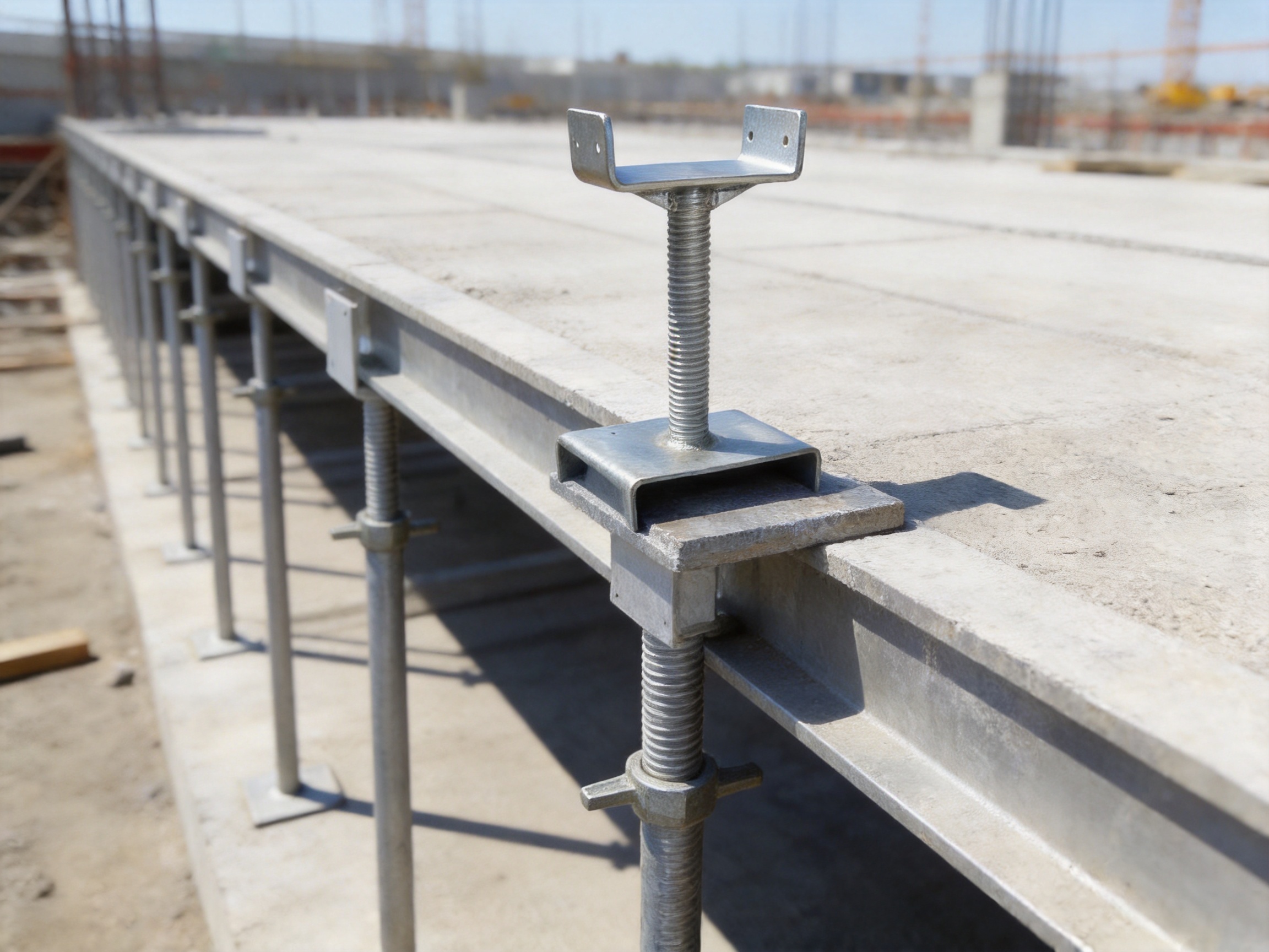
In plane or slab formwork, the U-head jack base is installed on top of vertical props or scaffold standards. The U-shaped head receives the primary beam, while secondary members and panels are placed above it. Workers adjust each support point to create a level and stable formwork surface.
This arrangement is effective for floor slabs, roof slabs, bridge decks, and other horizontal concrete elements. The adjustment mechanism allows the crew to compensate for uneven floor conditions and establish a consistent elevation across a large area. The broad saddle reduces the chance of the primary beam sliding during installation and concrete placement.
Before pouring, the support grid should be inspected for verticality, spacing, bracing, contact condition, and adjustment security. The beam must sit fully within the U-shaped head, and no unauthorized packing materials should compromise the connection. The support system should be checked again after workers move across the formwork or load reinforcement steel onto the deck.
Application Scenario: Wall Formwork Support
Wall formwork requires accurate vertical alignment. If the top support is too high, too low, or not properly positioned, the wall panels may lean or develop uneven pressure during concrete placement. A U-head jack base can provide controlled adjustment for the upper support member and help maintain the intended geometry.
The component is especially useful where the wall support arrangement includes steel beams, adjustable props, or scaffold-based support towers. It can compensate for small differences in support height and create a more stable contact point between the vertical support and the formwork beam.
However, a U-head jack base does not replace wall ties, diagonal braces, anchors, or other required stabilization components. The complete wall formwork system must be designed to resist concrete pressure, wind, impact, and construction loads.
Application Scenario: Scaffolding and Temporary Works
In scaffolding applications, the U-head jack base is used as an adjustable upper accessory. It can support beams, working platforms, temporary roof structures, loading arrangements, or formwork members when connected to a properly designed scaffold system.
The component is particularly useful when a modular scaffold tower must be adjusted to a precise elevation. Workers can use the threaded mechanism to compensate for small differences in floor level or beam height. The U-shaped head also offers a more suitable interface for beams than a plain scaffold rosette or flat plate.
Scaffolding systems must be assembled according to approved procedures. The support tower should have sufficient bracing, base support, tie-ins, and load capacity. The U-head jack base should be used only within its specified adjustment range and working load.
Application Scenario: Precast Component Installation
Precast wall panels, floor slabs, beams, and other components often require temporary support during positioning and connection. The U-head jack base can be used to make controlled elevation adjustments while the component is being aligned.
Its adjustment capability is useful when the supporting surface is not perfectly level or when several temporary supports must be synchronized. By providing a firm top saddle and a measurable adjustment mechanism, it can help workers achieve better verticality and flatness during installation.
Temporary supports for precast components must be designed according to the weight, lifting condition, wind exposure, connection sequence, and stability requirements of the project. The U-head jack base is one part of that system and should not be treated as an independent substitute for engineering design.
Installation and Operating Guidance
Prepare the Support Surface
The lower support surface should be firm, clean, and capable of carrying the design load. Loose soil, standing water, debris, or weak concrete can affect the stability of the entire support system. Where required, a suitable base plate, sole plate, or adjustable base should be used.
Check the Components
Before installation, inspect the U-head jack base for bent plates, damaged threads, cracked welds, missing handles, severe corrosion, or coating damage. The adjustment mechanism should rotate smoothly. Any component with visible structural damage should be removed from service and evaluated by a qualified person.
Install the Vertical Support
Place the jack base on the compatible vertical support member. Ensure that the connection is fully engaged and that the component is aligned with the centerline of the prop or scaffold standard. Avoid eccentric installation unless it is specifically allowed by the engineering design.
Position the Beam
Place the primary formwork beam into the U-shaped saddle. The beam should be fully seated and supported across the intended contact area. Do not use a beam that is too narrow, unstable, or incompatible with the saddle dimensions.
Adjust the Height
Rotate the handle or adjustment collar gradually to achieve the required elevation. Use a level, laser level, survey instrument, or other suitable measurement method to verify the formwork position. Avoid exceeding the recommended adjustment range because excessive extension can reduce stability and load capacity.
Complete System Bracing
Install horizontal and diagonal bracing, ties, connectors, and other required stabilization components. The U-head jack base provides top support and height adjustment, but it does not independently prevent all forms of lateral movement or buckling.
Inspect Before Loading
Before placing reinforcement, workers, equipment, or concrete, inspect the complete system. Confirm that the supports are vertical, the heads are properly seated, the threads are engaged, the bases are stable, and the adjustment components are secure. Recheck the system after significant loading or movement.
Maintenance and Reuse
U-head jack bases are designed for repeated use when handled and maintained correctly. After removal from a project, clean off concrete, mud, grease contamination, and other materials that may interfere with the threads or saddle surface.
Inspect the U-shaped head for deformation, cracks, excessive wear, and damage from impact. Check the threaded rod and nut for stripped threads, deep corrosion, bending, or unusual looseness. The handle should remain firmly attached and capable of rotating the adjustment mechanism.
Galvanized components should be stored in a dry and ventilated area where possible. If components are stacked while wet, trapped moisture can create white rust or localized corrosion on the zinc coating. Damaged galvanized areas should be evaluated and repaired according to the applicable coating repair procedure.
Do not straighten severely bent components by uncontrolled heating or impact. Do not weld unauthorized repairs onto load-bearing areas. Any repair, modification, or re-rating should be reviewed by a qualified engineer or the original manufacturer.
Customization and OEM Services
Construction projects often use different beam dimensions, scaffold standards, support tube diameters, and load requirements. A standard U-head jack base may not always provide the best fit. OEM customization allows the component to be adapted to a specific support system while maintaining controlled manufacturing and inspection.
Possible customization options include U-head width, saddle depth, plate thickness, support tube diameter, threaded rod size, adjustment range, handle configuration, reinforcement design, base connection, surface treatment, marking, and packaging.
Customers can provide drawings, samples, technical specifications, load requirements, or application photographs. Hyson’s engineering and production teams can review the proposed design, identify manufacturing considerations, and prepare a solution for approval before mass production.
Customization should be based on engineering requirements rather than visual preference alone. The manufacturer may need information about beam type, support spacing, expected load, adjustment frequency, environmental exposure, applicable standards, and installation method. This information helps ensure that the final component is suitable for actual site conditions.
For large infrastructure projects, OEM supply can also include batch traceability, inspection reports, coating documentation, packaging instructions, product labels, and delivery coordination. These services help contractors and distributors manage quality across large quantities of support components.
Why Choose an Experienced Heavy Steel Manufacturer?
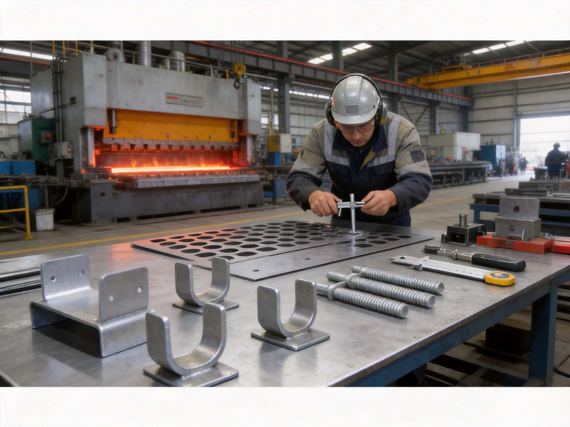
The U-head jack base may be a relatively compact item, but it requires control over several manufacturing disciplines. Cutting accuracy affects fit-up. Forming accuracy affects the saddle shape. Welding quality affects structural integrity. Thread machining affects adjustment performance. Galvanizing affects durability. Packaging affects the condition in which the product reaches the customer.
A manufacturer with integrated heavy steel fabrication capabilities can coordinate these operations more effectively than a supplier that only performs final assembly. Nantong Hyson Road And Bridge Formwork Co., Ltd. combines laser cutting, bending, forming, welding, machining, and surface treatment capabilities for construction steel products.
The company’s experience with custom formwork and infrastructure components also supports better communication between product design and site application. Instead of treating the U-head jack base as an isolated hardware item, the manufacturer can consider how it interacts with steel props, scaffolding, beams, formwork panels, concrete loads, and temporary works procedures.
Hyson’s experience serving major contractors and infrastructure projects has helped establish a quality-oriented manufacturing approach. Its products are made for construction environments where safety, repeatability, delivery reliability, and compatibility are important procurement considerations.
The company provides OEM and custom fabrication services for customers worldwide. Its manufacturing range extends beyond U-head jack bases to include bridge formwork, tunnel formwork, hydraulic tunnel trolleys, ringlock scaffolding, steel props, industrial steel structures, heavy steel components, and CNC steel plate processing.
Comparison with Alternative Products
| Support Solution | Main Strength | Typical Limitation | U-Head Jack Base Advantage |
|---|---|---|---|
| Flat adjustable top plate | Simple and economical support | Limited lateral beam retention | U-shaped saddle provides a more secure beam seat |
| Fixed-length steel prop | Strong vertical support | Little or no fine adjustment | Threaded mechanism allows controlled height correction |
| Timber packing or wedges | Easy to obtain on some sites | Variable compression and inconsistent accuracy | Manufactured adjustment gives more repeatable positioning |
| Specialized single-system connector | Good fit within one system | Limited cross-system compatibility | Standardized design can support various systems |
| Unprotected steel accessory | Low initial purchase cost | Higher corrosion exposure | Hot-dip galvanized surface improves durability |
| Low-quality cast or welded accessory | May appear economical | Inconsistent dimensions or structural quality | Controlled steel fabrication and inspection support reliability |
The most suitable support accessory depends on the project design, load requirements, local regulations, and installation method. The U-head jack base is particularly advantageous where secure top engagement, fine elevation control, reusable construction equipment, and broad system compatibility are important.
Safety Considerations
All temporary support systems should be designed, installed, inspected, and dismantled by competent personnel. The stated product capacity should not be interpreted as permission to exceed the capacity of the surrounding support system. The weakest component, connection, foundation, or bracing condition may govern the actual safe working load.
Loads should be applied concentrically wherever possible. Eccentric loading, impact loading, unsupported beam ends, excessive extension, inadequate bracing, and unstable ground can reduce the performance of the U-head jack base. Workers should follow approved method statements and project-specific safety procedures.
The adjustment mechanism must remain clean and properly engaged. Do not use damaged threads, missing locking components, cracked welds, heavily deformed heads, or severely corroded parts. Do not strike the adjustment handle with a hammer unless a specific procedure permits it.
During concrete placement, monitor the formwork for unusual movement, settlement, noise, or deformation. If instability is observed, stop work and evacuate the affected area until the support arrangement has been inspected by qualified personnel.
Inspection Checklist
A practical inspection checklist can help ensure consistent use of the product:
Confirm that the U-head jack base matches the approved drawing or system specification.
Check the steel body, saddle, base, and reinforcement parts for deformation or cracking.
Inspect the galvanized coating and identify areas of severe corrosion or mechanical damage.
Rotate the adjustment mechanism and confirm smooth, controlled movement.
Verify that the thread is fully engaged and that the adjustment range is not exceeded.
Confirm that the vertical support is compatible with the jack base connection.
Ensure that the beam is fully seated in the U-shaped head.
Check that the support is vertical and that the load path is aligned.
Verify the condition of the floor, base plate, sole plate, and surrounding support area.
Confirm that all required bracing, ties, and locking components are installed.
Inspect the system again after loading and during concrete placement where required.
Frequently Asked Questions
What is the main purpose of a U-head jack base?
The main purpose is to connect a vertical support to a formwork beam while providing controlled height adjustment. Its U-shaped head supports and helps retain the beam, while its threaded mechanism allows workers to fine-tune the elevation.
Can a U-head jack base be used with steel props?
Yes. It is commonly used with compatible steel props and adjustable support members. The connection dimensions, thread size, load rating, and operating range should be confirmed before installation.
Can it be used with ringlock or disc-lock scaffolding?
It can be used with compatible ringlock or disc-lock scaffolding uprights when the complete scaffold support system is designed for the intended application. Compatibility must be verified through dimensions and approved technical information.
What is the typical adjustment range?
A typical adjustment range is approximately 30 millimeters to 150 millimeters, although the exact range depends on the model, threaded rod length, head design, and customer requirements.
How accurate is the height adjustment?
Under suitable operating conditions, the adjustment accuracy can reach approximately plus or minus 0.5 millimeters. Actual accuracy depends on thread quality, measurement equipment, loading condition, installation practice, and operator control.
What materials are commonly used?
Q235 and Q345 carbon steels are commonly used for the main structural parts. The final material grade should be selected according to the required load, forming process, welding procedure, and project specification.
How much load can one U-head jack base support?
Depending on the model and verified working condition, a single support may carry approximately 80 kilonewtons to 120 kilonewtons. The allowable working load must be confirmed for the complete system, including the prop, thread, beam, base, bracing, and foundation.
Is the product corrosion resistant?
The product can be hot-dip galvanized, with a typical coating thickness of at least 75 micrometers. This improves resistance to humid and outdoor construction environments. Proper storage, handling, cleaning, and inspection are still required.
Can the U-shaped head be customized?
Yes. The saddle width, depth, plate thickness, reinforcement, connection dimensions, adjustment range, handle design, and surface treatment can be customized according to approved technical requirements.
Can the product support wall formwork?
Yes. It can be used as part of a wall formwork support arrangement to help adjust the top support and maintain alignment. It must be combined with suitable wall ties, braces, anchors, and other components required by the formwork design.
Can it be used for precast components?
Yes. It can provide temporary height adjustment during the installation of precast wall panels, floor slabs, beams, and similar components. The temporary support must be designed for the component weight, installation sequence, wind, stability, and connection conditions.
Does the U-head jack base replace bracing?
No. The U-head jack base provides top support and vertical adjustment, but it does not replace horizontal bracing, diagonal bracing, ties, anchors, or other stability components. The complete support system must be properly designed and assembled.
How should used components be maintained?
Clean concrete and debris from the saddle and threads, inspect for deformation and cracks, check thread operation, monitor corrosion, and store the components in a dry and ventilated area. Damaged parts should be removed from service.
What information is needed for an OEM quotation?
Useful information includes drawings, beam dimensions, support connection dimensions, required adjustment range, working load, material preference, surface treatment, applicable standards, order quantity, packaging requirements, and delivery destination.
Conclusion
The U-head jack base is a practical and high-value component for formwork, scaffolding, temporary works, and precast construction. Its combination of a secure U-shaped saddle, precision threaded adjustment, high-strength steel construction, and corrosion-resistant surface treatment gives it clear advantages over simple flat plates, fixed supports, and improvised packing methods.
By improving the connection between the vertical support and the formwork beam, the product helps reduce beam movement, distribute loads more evenly, and achieve more accurate elevation control. Its compatibility with steel props, ringlock scaffolding, disc-lock scaffolding, wall formwork, plane formwork, and precast support systems makes it suitable for many construction applications.
The manufacturing process is equally important. Accurate laser cutting, controlled forming, reliable welding, precision thread production, hot-dip galvanizing, and final inspection all contribute to consistent product performance. Nantong Hyson Road And Bridge Formwork Co., Ltd. combines these capabilities with experience in custom formwork, scaffolding, infrastructure steelwork, and heavy metal fabrication.
For contractors, distributors, and engineering procurement teams, the best solution is not simply the lowest-cost adjustable support. It is a component that fits the intended system, performs reliably under load, can be adjusted efficiently, withstands the construction environment, and is supported by dependable manufacturing and quality control. With standard and customized options available, the U-head jack base provides a strong foundation for accurate, efficient, and safer formwork support.
References
1. International Organization for Standardization, ISO 9001 Quality Management Systems: Requirements.
2. European Committee for Standardization, EN 74 Couplers, Spigot Pins and Baseplates for Use in Falsework and Scaffolding.
3. British Standards Institution, BS 1139 Metal Scaffolding Materials.
4. American Welding Society, Structural Welding Code and Welding Quality Guidance.
5. General principles of temporary works design, formwork support, scaffolding stability, and construction load management.
6. Manufacturer technical information for adjustable U-head jack bases, steel props, scaffolding accessories, and custom formwork components.
Product: U-head Jack Base



- Location
- Group 3, Fangzhuang Village, Rucheng Subdistrict, Rugao City, Nantong, Jiangsu, China
- Follow us
- Phone
- +86-13646196162
- info@hysonindustry.com
