 +86-13646196162
 info@hysonindustry.com




 русский
  عربى
عربى 


High-Precision Steel Molds for Interlocking Coastal Protection Blocks
 2026.07.25
Content
- 1 Why Coastal Protection Blocks Require Specialized Molds
- 2 Product Overview
- 3 Precision Geometry for Reliable Interlocking Performance
- 4 Symmetrical Split Design for Smooth Demolding
- 5 Steel Construction for Repeated Project Use
- 6 Manufacturing Process and Quality Control
- 7 Advantages Over Conventional or Low-Precision Molds
- 8 Application in Deep-Water Breakwaters
- 9 Application in Port Expansion Projects
- 10 Application in Coastal Erosion Defense
- 11 Type A and Type B Model Options
- 12 Concrete Casting Considerations
- 13 Demolding and Handling Procedure
- 14 Inspection and Maintenance for Long Service Life
- 15 Advanced Manufacturing Strengths
- 16 Integrated Steel Processing Capability
- 17 Customization for International OEM Projects
- 18 Project and Commercial Benefits
- 19 Safety and Operational Discipline
- 20 Selection Checklist for Buyers
- 21 Frequently Asked Questions
- 21.1 What is an Accropod Formwork/Mold used for?
- 21.2 Why is a steel mold preferred for large coastal blocks?
- 21.3 How does the symmetrical split design improve production?
- 21.4 What problems can occur if the mold angles are inaccurate?
- 21.5 What are Type A and Type B models?
- 21.6 Can the mold be customized?
- 21.7 What manufacturing technologies are used?
- 21.8 How can the mold reduce production costs?
- 21.9 How should the mold be maintained?
- 21.10 Does the mold replace coastal engineering design?
- 21.11 What information should be provided when requesting a quotation?
- 22 Conclusion
- 23 References
- 24 Product: Accropod Formwork/Mold
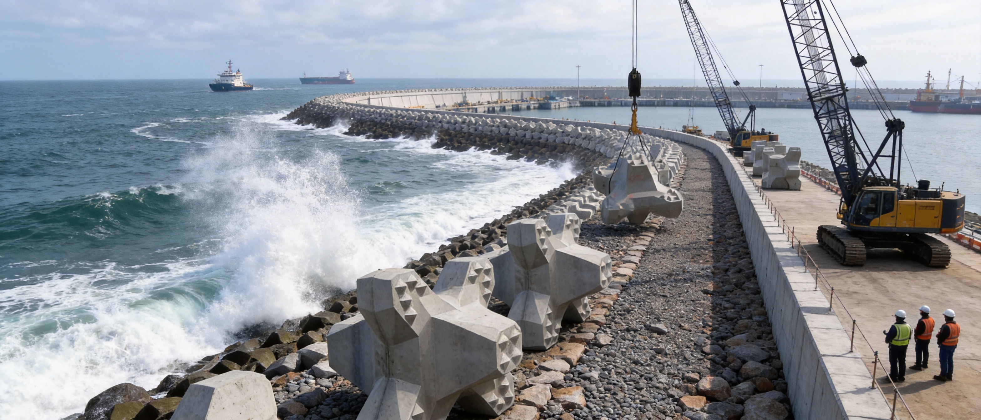
Coastal infrastructure is exposed to some of the most demanding conditions in civil engineering. Breakwaters, seawalls, harbor extensions, navigation channels, and shoreline protection systems must withstand repeated wave impact, tidal movement, saltwater corrosion, abrasion, hydraulic uplift, and long-term changes in the seabed. A protection system may contain thousands of individual concrete armor units, and the performance of the entire structure depends on the accuracy, consistency, and durability of every unit.
For this reason, the production mold is much more than a temporary container for concrete. It is a precision engineering tool that determines the geometry, surface quality, dimensional repeatability, demolding performance, and interlocking behavior of each coastal protection block. When the armor unit has a complex three-dimensional shape, even a small deviation in an angle, joint, edge, or internal transition can affect casting quality and the final stability of the completed revetment.
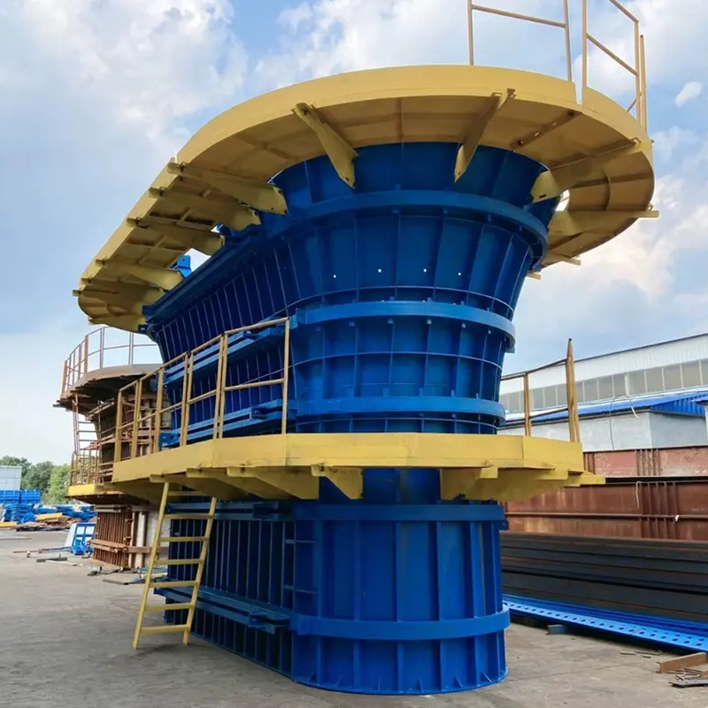
The Accropod Formwork/Mold is a specialized steel mold developed for the production of Accropod Twist Blocks and similar interlocking coastal protection modules. Its purpose is to reproduce a complex, high-performance geometry accurately while allowing concrete units to be cast, cured, and removed efficiently. The mold combines precision CNC laser cutting, carefully controlled steel fabrication, a symmetrical split structure, and practical features designed for repeated construction-site use.
Compared with basic fabricated molds, the system provides better control over critical dimensions, smoother opening and closing, improved protection of concrete edges, and more dependable production consistency. It is suitable for projects where the quality of precast armor units directly affects wave energy dissipation and the long-term reliability of coastal infrastructure.
Why Coastal Protection Blocks Require Specialized Molds
Traditional concrete blocks with relatively simple rectangular or trapezoidal forms can often be manufactured using uncomplicated molds. Interlocking armor units are different. Their shape is intentionally irregular, with multiple faces, inclined surfaces, projections, recesses, and contact zones. These features allow neighboring units to connect mechanically and form a stable protective layer. However, the same features make the mold more difficult to design, fabricate, assemble, and remove.
A complex armor block must satisfy several requirements at the same time. Its overall dimensions must remain within the required tolerance. Its contact surfaces must be positioned correctly so that blocks can interlock without excessive gaps. Its corners must be sufficiently strong to withstand handling and placement. Its surface should be free from major voids, tearing, and defects. The mold must also open without damaging the fresh or partially cured concrete.
If the mold is inaccurate, the resulting block may have an incorrect center of gravity, uneven contact surfaces, or distorted projections. These problems can reduce the stability of the armor layer. A block that does not fit correctly may rotate, settle excessively, or create an undesirable concentration of wave force. In a large breakwater, minor production inconsistencies can accumulate across a substantial area.
Mold design therefore has a direct relationship with hydraulic performance. The interlocking geometry must be reproduced reliably so that the finished units can work together as intended. Precision molding supports predictable placement, consistent void ratios, controlled permeability, and stable transfer of wave forces through the armor layer.
Product Overview
The Accropod Formwork/Mold is a reusable steel casting mold for producing complex concrete coastal protection units. It is designed around the geometry of interlocking T-shaped or twisted armor blocks and is available in Type A and Type B configurations to accommodate different project requirements and block tonnages.
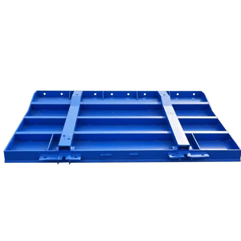
The mold consists of accurately fabricated steel panels and supporting components arranged in a split configuration. During casting, the sections are secured to create the complete block cavity. After the concrete has reached the appropriate demolding strength, the mold sections can be separated in a controlled sequence. This approach reduces friction between the steel and concrete and helps preserve delicate edges and corners.
The design is intended for repeated use in precast yards or project-based production facilities. Depending on the block size, concrete mix, handling method, curing conditions, and maintenance program, the mold can support continuous production while retaining geometric consistency. The steel construction also makes the mold suitable for demanding working environments where it may be moved, cleaned, assembled, and reused many times.
Although the mold is manufactured for a specific block geometry, it can be engineered according to project drawings, required block weight, production method, lifting arrangements, and local site conditions. Customization may include dimensional adjustments, reinforcement details, lifting points, locking systems, identification marks, and surface treatment.
| Item | Typical Description | Project Benefit |
|---|---|---|
| Product type | Reusable steel formwork and casting mold | Supports repeat production of coastal armor units |
| Primary application | Breakwaters, revetments, port protection, and erosion control | Suitable for marine and shoreline infrastructure |
| Block geometry | Complex interlocking three-dimensional form | Promotes mechanical stability within an armor layer |
| Configuration | Symmetrical split mold structure | Improves opening, closing, and demolding performance |
| Available models | Type A and Type B | Provides flexibility for different project tonnages |
| Manufacturing method | CNC laser cutting, bending, fitting, and certified welding | Improves dimensional accuracy and repeatability |
| Customization | Engineering based on block drawings and project requirements | Allows OEM supply for specialized applications |
Precision Geometry for Reliable Interlocking Performance
The main technical challenge in producing an interlocking armor unit is controlling its three-dimensional geometry. Each face and transition contributes to the way the block contacts neighboring units. If one section is too large, too small, too steep, or too shallow, the finished block may not sit in the intended position.
The mold is produced using precision CNC laser cutting technology. Digital drawings are converted into controlled cutting paths so that steel plates and profiles can be manufactured with consistent dimensions. Laser processing provides narrow cutting tolerances, clean edges, and repeatable results across multiple parts. This is particularly important when several panels must meet at compound angles.
After cutting, the components undergo forming, edge preparation, fitting, and dimensional inspection. The fabrication sequence is planned to reduce distortion and preserve the relationship between critical reference points. When welding is required, the welding procedure and sequence are controlled to minimize heat-related deformation. The finished mold is then checked against the approved geometry before delivery.
Accurate geometry provides several benefits. It helps ensure that concrete fills the cavity evenly. It reduces unexpected thin sections and excessive corners. It supports consistent block weight and volume. It also improves the repeatability of block placement because operators are working with units that share the same basic dimensions and contact characteristics.
In addition, precision reduces the risk of defects caused by angular mismatch. A poorly aligned mold section may create a step or ridge that catches concrete during demolding. It may also produce an edge that is weaker than the design requires. By controlling the angles at the manufacturing stage, the mold helps prevent such problems before concrete is introduced.
Symmetrical Split Design for Smooth Demolding
Demolding is one of the most important stages in the production of complex armor blocks. Concrete has a high compressive strength, but newly cast units can still be vulnerable at sharp corners, projections, and thin transitions. If a mold is pulled away in the wrong direction, the concrete may adhere to the steel, causing edge breakage, surface tearing, or partial damage to the block.
The symmetrical split design addresses this issue by dividing the mold into balanced sections that can be opened in a controlled and predictable manner. Instead of forcing a complex block out of a single rigid cavity, the operator separates the mold around the concrete unit. The movement path is arranged to reduce interference between the steel panels and the block geometry.
A balanced split also improves assembly. When the two sides are correctly aligned, the cavity closes around the block shape with fewer opportunities for offset or uneven contact. Locking points can be positioned for practical access, and the operator can visually check the joints before casting. This supports a more efficient production cycle.
The design is especially useful for large blocks, where the weight of the concrete increases the consequences of demolding errors. By reducing friction and avoiding unnecessary impact, the mold helps protect corners and contact projections. Less damage means fewer repair operations, less material waste, and more usable blocks available for placement.
Smooth demolding also contributes to labor safety. Operators do not need to apply excessive force or improvise with unsuitable tools to release the block. A defined opening sequence makes the work easier to standardize, which is valuable when multiple crews are producing units on a daily basis.
Steel Construction for Repeated Project Use
Marine construction projects often require large quantities of armor units. A mold must therefore tolerate repeated loading, vibration, cleaning, handling, and exposure to wet concrete. The steel structure is designed to provide sufficient rigidity so that the cavity does not change shape during casting or lifting.
Rigid construction is important because concrete pressure acts against the mold walls while the material is being placed and compacted. If a panel bends, even slightly, the resulting unit may vary from the intended geometry. Repeated deformation can also enlarge joints and accelerate wear. A robust frame and properly located reinforcement help maintain alignment throughout the production cycle.
The mold may be used with different concrete placement methods, including crane bucket placement, pump placement, or other project-specific procedures. The selected process influences the local pressure and vibration applied to the mold. For this reason, the final design should be reviewed according to the concrete mix, unit size, casting sequence, and compaction method.
Steel surfaces can be prepared and treated to support easier cleaning and improved service life. Appropriate release agents should be selected for the concrete mix and applied uniformly. After each casting cycle, the mold should be cleaned without damaging the steel surface or altering the edges of the cavity. Regular inspection of locks, hinges, lifting points, welds, and contact surfaces is recommended.
With proper use, a reusable steel mold can provide a lower cost per unit than disposable or improvised casting arrangements. Its value is not limited to the initial purchase price. A reliable mold can reduce labor, shorten production cycles, minimize rejected blocks, and improve the predictability of the entire precast operation.
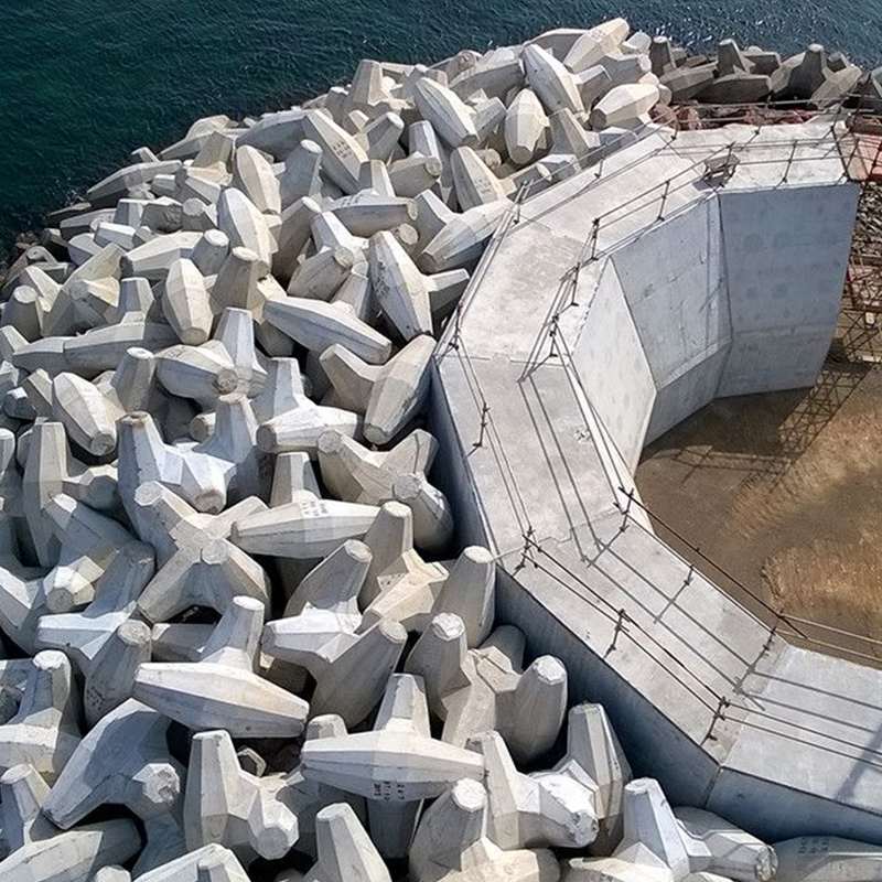
Accropod Formwork/Mold
Manufacturing Process and Quality Control
Engineering Review and Drawing Confirmation
Manufacturing begins with a review of the block design, project specifications, and production requirements. The mold supplier examines the approved block geometry, nominal weight, dimensions, demolding direction, lifting method, and expected quantity. Any unclear dimensions or conflicting details should be resolved before cutting begins.
The engineering review also considers the practical conditions of the precast yard. The mold may need to work with an existing casting platform, crane system, concrete delivery method, or curing arrangement. Access for workers, cleaning clearance, and the location of locking components are evaluated so that the finished tool is not only accurate but also convenient to operate.
For customized projects, three-dimensional data can be used to verify the cavity and split lines. The mold sections are analyzed to identify possible undercuts, narrow openings, difficult corners, and areas where concrete may become trapped. This digital review helps reduce the possibility of redesign after fabrication.
CNC Laser Cutting
Once the drawings are approved, steel plates are cut using CNC laser equipment. Computer-controlled processing maintains consistency between corresponding parts and allows complex profiles to be produced without the variation associated with manual cutting. The process also supports efficient nesting of parts, helping reduce material waste.
Laser-cut edges are inspected for dimensional accuracy, heat effects, burrs, and surface condition. Where required, edges are prepared for bending or welding. Reference marks can be added to support accurate assembly and reduce the chance of installing similar components in the wrong position.
Forming and Assembly
Some mold panels require bending or forming to create the correct three-dimensional surfaces. These operations are carried out according to the approved drawings. Formed parts are checked against templates, gauges, or digital measurements before they are fitted into the assembly.
Assembly requires careful control of alignment. The mold is built around reference points so that the relationship between opposite panels, split lines, and locking locations remains accurate. Temporary fixtures may be used to hold components in position during tack welding and inspection.
Certified Welding
Welding connects the fabricated parts and provides the structural integrity needed for repeated casting. Controlled welding procedures help reduce distortion and improve the consistency of the completed mold. The welding process can be performed in accordance with recognized AWS or EN practices, depending on the project requirements.
Weld quality is important in both structural and functional areas. A weak frame weld may affect alignment under load, while a rough internal weld may interfere with demolding or leave marks on the concrete. Welds in the cavity area are therefore treated and finished as necessary to provide a suitable surface.
Dimensional Inspection
After fabrication, the mold is inspected at multiple stages. Critical dimensions include overall length, width, height, diagonal measurements, panel angles, split-line alignment, locking positions, and the relationship between projections and recesses. The inspection method may include calibrated measuring tools, templates, three-dimensional measurement, and trial assembly.
A complete dry assembly allows the production team to verify that the mold opens and closes smoothly. It also confirms that the sections can be handled safely and that all locking devices are accessible. Any interference or excessive gap can be corrected before shipment.
Surface Treatment and Delivery Preparation
Depending on the order requirements, the mold may receive surface cleaning, primer, protective coating, identification marks, and packaging for transport. Contact surfaces must be protected from impact during loading and unloading. Components are labeled so that assembly at the job site is straightforward.
Documentation may include assembly drawings, inspection records, operating instructions, maintenance recommendations, and a list of included components. Clear documentation supports faster commissioning and helps operators use the mold according to the intended procedure.
Advantages Over Conventional or Low-Precision Molds
The market includes many types of concrete casting molds, including wooden forms, simple welded boxes, fiberglass molds, plastic molds, and general-purpose steel forms. These alternatives may be suitable for uncomplicated shapes or short production runs. However, complex interlocking armor units place greater demands on accuracy, rigidity, and demolding control.
Better Dimensional Repeatability
Low-precision molds may rely heavily on manual cutting, fitting, or field adjustment. Small differences between mold units can lead to inconsistent block dimensions. The Accropod mold uses digital fabrication and controlled assembly to provide a more repeatable cavity, which helps maintain consistency across a large production batch.
Improved Protection of Edges and Corners
Many conventional molds are designed as rigid boxes that require the concrete unit to be lifted or forced out. This approach can be unsuitable for blocks with projections and complex contact surfaces. The symmetrical split structure provides a more controlled release path and reduces the mechanical stress placed on vulnerable concrete edges.
Greater Structural Rigidity
Improvised forms may move or deform under concrete pressure, especially when the unit is large or the concrete is heavily vibrated. A properly engineered steel mold provides stronger resistance to deformation. This helps preserve the block geometry and reduces the risk of repeated dimensional drift.
More Efficient Production
A mold that opens smoothly can reduce cycle time. The operator can place reinforcement, apply release agent, assemble the panels, cast the concrete, and demold the unit according to a repeatable sequence. Reduced repair work also improves productivity because labor can focus on production rather than correcting damaged blocks.
Better Suitability for Industrial Projects
Large coastal projects require traceability and quality control. A precision steel mold is easier to inspect, identify, maintain, and standardize than a temporary form assembled directly on site. It is more compatible with project quality plans and with the production records required for major infrastructure work.
| Comparison Factor | Low-Precision or Improvised Form | Precision Steel Accropod Mold |
|---|---|---|
| Geometry control | Dependent on manual fabrication and adjustment | Supported by CNC cutting and controlled assembly |
| Demolding | May require force or repeated adjustment | Designed for controlled separation through split sections |
| Block consistency | Potential variation between casting cycles | Improved repeatability for large production batches |
| Corner protection | Higher risk of chipping during release | Reduced interference around projections and edges |
| Rigidity | May deform under concrete pressure | Heavy steel construction supports shape retention |
| Production efficiency | More repair and adjustment time | Faster standardized operating cycle |
| Project suitability | Best for basic shapes or temporary work | Suitable for demanding marine infrastructure |
Application in Deep-Water Breakwaters
Deep-water breakwaters face strong wave loading and often require a durable outer armor layer. Interlocking concrete units are placed on the seaward slope to dissipate wave energy and protect the underlying core and filter layers. The stability of the armor layer depends on the unit shape, mass, placement pattern, and interaction between adjacent units.
A high-quality mold helps produce units with consistent contact geometry. When placed according to the engineering design, the blocks can form a stable layer with controlled voids and multiple points of mechanical interaction. The result is a protective surface that resists displacement and reduces the transmission of wave energy toward the structure behind it.
Deep-water projects also benefit from reliable production because the number of units may be very large. Rejected blocks are costly to replace, particularly when the casting yard is far from the placement area or when marine equipment is scheduled according to a narrow weather window. Reducing production defects supports more efficient use of cranes, barges, transport vehicles, and placement crews.
Application in Port Expansion Projects
Port expansion often involves reclamation, new breakwaters, quay protection, channel construction, and the development of cargo-handling areas. Newly created land and exposed marine structures may be vulnerable to wave attack before the final port facilities are completed. Armor blocks provide an important line of defense during both construction and operation.
The mold can support production near the project site, reducing dependence on distant precast suppliers. Local production may simplify logistics and allow the construction team to adjust output according to the progress of earthworks, rock placement, and marine installation. It also gives project managers greater control over inspection and acceptance procedures.
Where a port project requires different armor weights for different water depths or slope sections, Type A and Type B mold configurations can provide useful flexibility. Customized versions may also be developed for project-specific block dimensions, provided the final geometry is confirmed by the responsible engineering team.
Application in Coastal Erosion Defense
Coastal highways, urban shorelines, industrial waterfronts, and public facilities may be exposed to progressive erosion. In these areas, an interlocking armor layer can protect the slope and help prevent the loss of supporting soil or fill. The blocks may be installed along a revetment, at the toe of a slope, around an inlet, or near a structure that requires additional wave protection.
Coastal erosion projects often have restricted access and limited working space. A reusable mold can be transported to a suitable casting location and used to produce units in a controlled environment. Consistent block quality is particularly important where the units must fit around drainage structures, access roads, culverts, or other existing facilities.
The mold itself does not replace hydraulic design, foundation preparation, filter layers, or proper placement. Instead, it supports the manufacturing stage by helping ensure that the selected armor unit is produced according to the required geometry. Successful erosion control depends on the complete system, including geotechnical design, wave analysis, drainage, toe protection, and construction supervision.
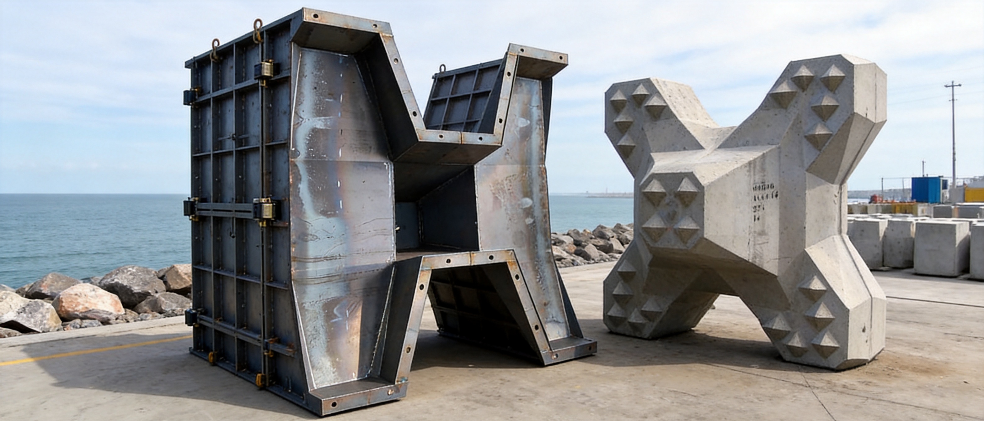
Type A and Type B Model Options
Different coastal projects require different armor unit weights and dimensions. Water depth, design wave height, slope angle, seabed conditions, exposure direction, and the importance of the protected asset all influence the selection of the concrete block. Offering Type A and Type B configurations allows the mold system to serve more than one standard production requirement.
The two models should not be selected solely by appearance. The correct choice must correspond to the approved block drawings and the structural or hydraulic calculations for the project. The block mass, cavity dimensions, lifting method, concrete volume, and placement equipment should be confirmed before the order is finalized.
Where neither standard model fully matches the project, an OEM version can be engineered. Custom design may involve new dimensions, adjusted split lines, special lifting arrangements, different panel thicknesses, or modifications to suit a local casting platform. The purpose of customization is to achieve the required production result without compromising the geometric and structural principles of the armor unit.
Concrete Casting Considerations
The mold is an important part of the production system, but the final quality of the armor block also depends on concrete materials and process control. The concrete mix should be selected according to the required strength, durability, workability, permeability, and exposure conditions. Marine projects commonly require careful consideration of chloride exposure, freeze-thaw conditions where applicable, abrasion, and long-term water absorption.
Before casting, the mold should be clean and free from hardened concrete, debris, standing water, and damaged release-agent buildup. The panels should be checked for correct alignment and securely locked. The internal surface should receive a uniform application of a suitable release agent. Excessive release agent can create surface defects, while insufficient coverage may increase adhesion.
Concrete should be placed in a sequence that limits segregation and ensures that narrow sections and internal corners are filled. Vibration or other compaction methods should be controlled so that the concrete becomes dense without causing the mold to move or the mix to segregate. The operator should monitor leakage at split lines and stop casting if a joint begins to open.
Curing is equally important. The unit should remain undisturbed until it reaches the specified demolding strength. Removing the mold too early can cause edge damage even when the mold itself is correctly designed. The curing method should be compatible with the concrete specification and the project schedule.
Demolding and Handling Procedure
A typical demolding sequence begins with a visual inspection of the concrete surface and confirmation that the unit has reached the required strength. Workers then release the locking devices in the prescribed order. The split sections are opened evenly, avoiding sudden impact or lateral dragging against the concrete.
If a panel does not release smoothly, operators should stop and identify the cause. Possible causes include inadequate release agent, concrete leakage into a joint, early demolding, mold misalignment, or a damaged panel edge. Forcing the mold open can damage both the block and the equipment.
Once the mold is removed, the block should be inspected for cracks, honeycombing, exposed aggregate, edge damage, dimensional irregularities, and other defects. Lifting should be performed using approved equipment and attachment points. Large units must be handled with consideration for their center of gravity and the capacity of cranes, slings, spreader beams, and transport vehicles.
After demolding, the steel panels should be cleaned and examined. Hardened concrete should be removed using methods that do not gouge the surface or deform the edges. Locks and hinges should be lubricated or serviced as appropriate. A simple mold-use record can document casting date, block number, operator, observations, repairs, and maintenance actions.
Inspection and Maintenance for Long Service Life
Regular inspection is a practical way to protect the accuracy and service life of the mold. The inspection frequency should reflect the production rate and working conditions. A heavily used mold in a marine precast yard may require inspection after every cycle, while more detailed dimensional checks can be scheduled at defined production intervals.
Operators should inspect split lines for deformation, gaps, or concrete buildup. They should also check locking pins, bolts, hinges, lifting lugs, support frames, welds, and contact surfaces. Any loose or damaged component should be repaired before the next casting cycle.
Dimensional checks are valuable because wear may develop gradually. A mold can continue to look serviceable while a joint or panel has moved enough to affect block quality. Periodic measurement against the approved drawing or a reference template can identify such changes before they become a major production problem.
Protective coatings should be repaired when damaged. Rust, especially at joints or water-trapping areas, can interfere with assembly and reduce the effective thickness of steel. Storage should be carried out on stable supports, with water allowed to drain and components protected from unnecessary impact.
Advanced Manufacturing Strengths
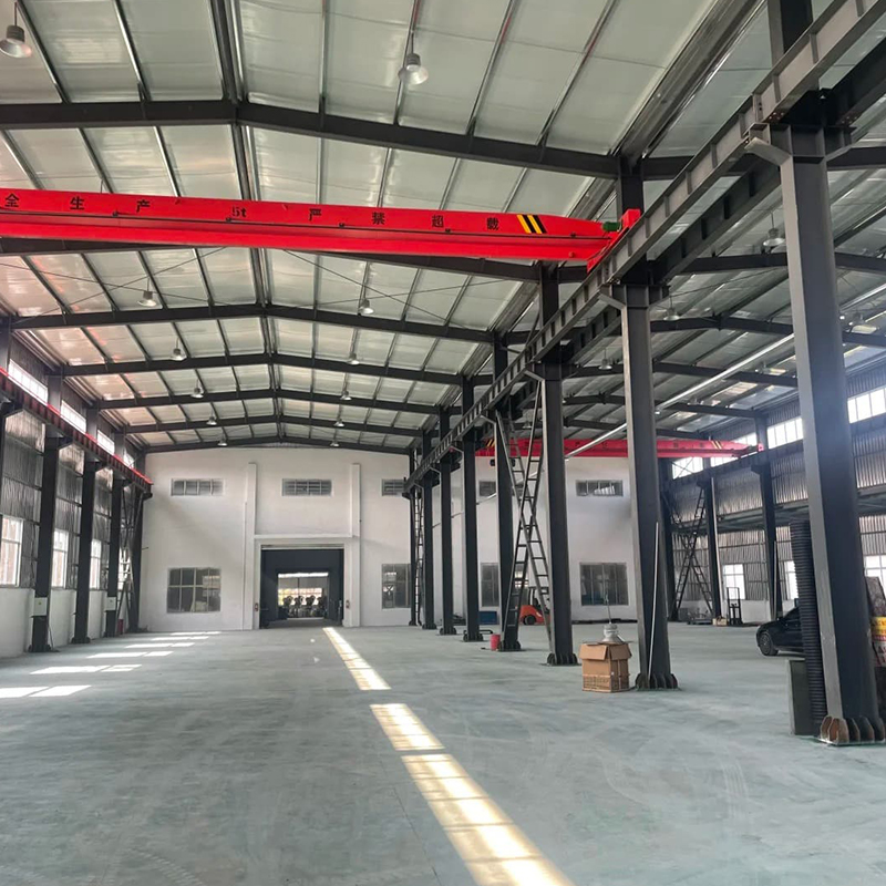
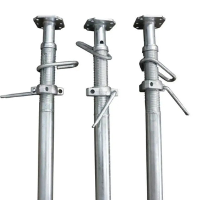
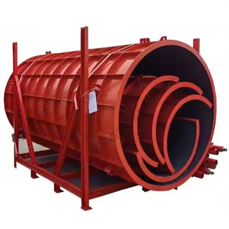
The manufacturer behind the mold operates as a heavy steel fabrication and infrastructure formwork supplier. Its production capability covers custom steel formwork, bridge and tunnel formwork, ringlock scaffolding, steel props, industrial steel structures, steel plate cutting, bending, welding, and OEM fabrication.
Advanced laser cutting equipment supports the production of complex parts with consistent profiles. Standardized production lines help coordinate material preparation, component fabrication, assembly, inspection, and finishing. This integrated approach is useful for non-standard molds because the supplier can control more stages internally rather than relying entirely on disconnected subcontractors.
Welding is performed according to recognized AWS and EN practices where required by the project. The company also works within ISO 9001 quality-management principles and manufactures products associated with BS1139 and EN74 requirements for applicable scaffolding lines. These standards and procedures demonstrate an established approach to documentation, process control, inspection, and product consistency.
The company holds 12 utility patents and has supplied major contractors and central state-owned enterprises, including CCCC and CRCC. Experience related to the Sutong Yangtze River Bridge, Taizhou Bridge, and Sudan Thermal Power Plant reflects exposure to large-scale construction environments where fabrication quality, delivery coordination, and compliance are essential.
This background is relevant to the production of breakwater molds. Coastal protection projects often require the same capabilities found in bridge and industrial fabrication: accurate drawings, thick steel processing, controlled welding, lifting analysis, quality records, protective finishing, and reliable delivery of oversized components.
Integrated Steel Processing Capability
A mold may require more than laser cutting. Steel plates can need bending, rolling, drilling, machining, edge preparation, welding, grinding, and coating. An integrated supplier can coordinate these operations to maintain the design intent across the complete assembly.
Laser cutting creates the initial precision, but fabrication discipline determines whether the final mold retains that precision. Bending must follow the correct radius and orientation. Fixtures must hold parts securely during assembly. Welding must be sequenced to limit distortion. Grinding must remove unsuitable projections without changing critical geometry. Inspection must verify the complete result rather than checking only individual parts.
The same capability allows the manufacturer to support related project requirements. A contractor purchasing a breakwater mold may also require steel platforms, access frames, lifting beams, temporary supports, scaffolding components, or custom structural parts. Coordinating multiple steel products through one qualified fabrication source can simplify communication and reduce interface risks.
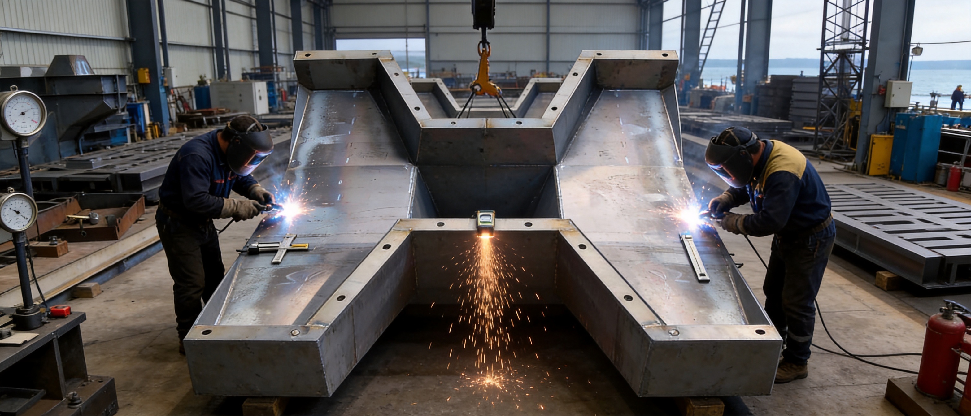
Customization for International OEM Projects
International coastal projects often differ in design standards, transport conditions, available equipment, labor practices, and inspection procedures. An OEM steel mold supplier must therefore be able to work from customer drawings, engineering data, or an agreed technical specification.
Customization can address the block size, nominal weight, mold material, panel thickness, support arrangement, lock design, lifting points, surface coating, marking system, and packaging method. The mold can also be adapted to the dimensions of an existing casting bed or to a specific crane and handling process.
Before production, the customer and supplier should confirm the approved geometry, material grade, weld standard, dimensional tolerances, inspection plan, delivery terms, and required documentation. A clear technical agreement reduces misunderstandings and ensures that the delivered mold is ready for the intended production method.
For large projects, pre-production review is recommended. This may include three-dimensional model checks, a trial assembly, sample measurements, and an inspection of the demolding sequence. Such steps are especially useful when the mold will be operated by a local team that requires clear instructions and training materials.
Project and Commercial Benefits
The economic value of a precision mold can be assessed through the complete production cycle rather than the initial equipment cost alone. A mold that reduces rejected blocks, shortens demolding time, and protects concrete edges can lower the overall cost of armor-unit production.
Consistent production also improves planning. When each casting cycle follows a similar sequence, managers can estimate concrete demand, labor requirements, crane utilization, curing space, transport capacity, and placement output more accurately. This is important for marine works, where weather and tide conditions may limit the available installation window.
Reduced repair work is another significant benefit. Damaged corners may require patching, inspection, and approval before a block can be used. Some defects may make a block unsuitable for the armor layer, resulting in material waste. By supporting smooth release and accurate geometry, the mold helps improve the percentage of accepted units.
A reusable steel mold also creates flexibility for phased projects. If the contractor must produce blocks for several sections over time, the same mold can be maintained and redeployed. This is different from one-time forms that may have limited durability or require extensive rebuilding after each phase.
Safety and Operational Discipline
Large concrete armor units and steel molds present significant lifting and handling risks. Safe operation requires a documented procedure, trained personnel, suitable lifting equipment, and regular inspection of all attachment points. Workers should not stand beneath suspended loads or place hands between mold sections during closing and opening.
The mold should be positioned on a stable, level casting surface capable of supporting the combined weight of the steel and wet concrete. The surrounding area should provide adequate access for concrete placement, vibration, inspection, and crane operation. Locking devices must be fully engaged before casting begins.
Protective equipment may include helmets, safety footwear, gloves, eye protection, hearing protection, and fall protection where elevated work is required. Welding, grinding, and coating activities must follow the safety requirements of the production facility and project site.
Clear operating instructions improve both safety and quality. The instructions should identify the assembly order, locking points, release sequence, approved lifting locations, cleaning method, inspection requirements, and response to abnormal resistance during demolding.
Selection Checklist for Buyers
When evaluating a supplier or comparing different molds, buyers should examine the complete technical and service package. The lowest initial quotation may not provide the best result if it excludes dimensional inspection, trial assembly, documentation, replacement components, or suitable surface protection.
The following questions can help guide procurement:
- Can the supplier manufacture the exact three-dimensional block geometry?
- Is the mold designed for the required block tonnage and concrete pressure?
- Which steel grades and thicknesses will be used?
- How are laser cutting, bending, assembly, and welding controlled?
- What dimensional tolerances will be verified before shipment?
- Does the split design allow practical and safe demolding?
- Are Type A, Type B, or customized configurations available?
- Will the mold be trial-assembled before delivery?
- Are lifting points and locking components included?
- What surface treatment and corrosion protection are provided?
- Are assembly drawings, inspection reports, and maintenance instructions supplied?
- Can the supplier provide replacement parts or technical support?
A technically capable supplier should be willing to discuss the casting process as well as the steel fabrication. The best result comes from matching the mold to the concrete mix, curing method, handling equipment, project schedule, and quality-assurance plan.
Frequently Asked Questions
What is an Accropod Formwork/Mold used for?
It is used to produce complex interlocking concrete armor units for coastal protection. These units are commonly installed on breakwaters, revetments, port structures, and erosion-control systems to dissipate wave energy and stabilize exposed slopes.
Why is a steel mold preferred for large coastal blocks?
Steel provides high rigidity, repeatable geometry, and durability under repeated casting cycles. It can withstand the pressure and handling demands associated with large concrete units and can be repaired or maintained for continued project use.
How does the symmetrical split design improve production?
The split design allows the mold sections to separate around the finished concrete unit instead of forcing the block out of a rigid cavity. This reduces friction, protects edges and projections, and supports a smoother, more predictable demolding cycle.
What problems can occur if the mold angles are inaccurate?
Angular inaccuracies may cause concrete adhesion, difficult demolding, edge breakage, dimensional inconsistency, poor interlocking, or incorrect block placement. In a large armor layer, these problems can affect construction efficiency and structural stability.
What are Type A and Type B models?
Type A and Type B are standard mold configurations intended to meet different block tonnage and project requirements. The correct model should be selected according to the approved engineering drawings and hydraulic design, not simply by visual preference.
Can the mold be customized?
Yes. OEM customization can include block dimensions, mold configuration, panel thickness, support frames, locking systems, lifting points, surface treatments, markings, and compatibility with a particular casting platform or handling system.
What manufacturing technologies are used?
The production process can include CNC laser cutting, steel plate forming, precision fitting, controlled welding, grinding, surface treatment, trial assembly, and dimensional inspection. The exact process depends on the approved design and project specification.
How can the mold reduce production costs?
It can reduce costs by lowering the rate of damaged or rejected blocks, shortening demolding time, limiting repair work, improving concrete-unit consistency, and supporting repeated use across a large project or multiple project phases.
How should the mold be maintained?
The mold should be cleaned after each casting cycle, checked for concrete buildup and deformation, lubricated or serviced at moving and locking components, protected against corrosion, and periodically measured against the approved geometry.
Does the mold replace coastal engineering design?
No. The mold supports the manufacturing of the selected armor unit. Hydraulic analysis, geotechnical design, foundation preparation, filter layers, toe protection, block placement, and construction supervision remain essential parts of a complete coastal protection system.
What information should be provided when requesting a quotation?
Buyers should provide block drawings or three-dimensional data, target block weight, required quantity, project location, casting method, concrete details, handling equipment, desired standards, delivery schedule, surface-treatment requirements, and any special inspection or documentation needs.
Conclusion
The quality of a coastal protection system begins before the concrete reaches the shoreline. It begins with the accuracy of the mold used to produce each armor unit. For complex interlocking blocks, the mold must reproduce three-dimensional geometry precisely, withstand repeated casting pressure, open without damaging the concrete, and remain practical for daily operation.
The Accropod Formwork/Mold addresses these requirements through CNC laser-cut components, controlled steel fabrication, a rigid construction, and a symmetrical split design. Its production advantages include improved dimensional repeatability, smoother demolding, better protection of concrete edges, reduced repair work, and greater suitability for high-volume marine construction.
Its value is further strengthened by the manufacturing capabilities of a supplier experienced in bridge formwork, heavy steel structures, scaffolding, steel plate processing, certified welding, and OEM fabrication. Integrated laser cutting, bending, welding, inspection, and quality control provide a dependable foundation for customized coastal protection equipment.
For deep-water breakwaters, port expansion, and erosion-defense projects, a precision steel mold can support more efficient production and more reliable armor-layer performance. When combined with correct concrete technology, proper curing, safe handling, disciplined maintenance, and approved coastal engineering design, it becomes an important tool for building durable marine infrastructure.
References
1. United States Army Corps of Engineers. Coastal Engineering Manual. Engineering guidance for waves, coastal structures, breakwaters, revetments, and shoreline protection.
2. Construction Industry Research and Information Association. Manual on the Use of Concrete Armor Units in Coastal and Marine Works.
3. International Organization for Standardization. ISO 9001, Quality Management Systems—Requirements.
4. American Welding Society. Structural Welding Code—Steel, AWS D1.1/D1.1M.
5. European Committee for Standardization. EN 74, Couplers, Spigot Pins and Baseplates for Use in Falsework and Scaffolds.
6. British Standards Institution. BS 1139, Metal Scaffolding Materials.
7. International Navigation Association. Guidelines for the Design and Construction of Maritime Structures and Breakwaters.
8. Neville, A. M. Properties of Concrete. Technical reference covering concrete materials, strength, durability, curing, and quality control.
9. National Research Council. Shore Protection Manual. Reference material on wave action, armor stability, and coastal structure design.
Product: Accropod Formwork/Mold


- Location
- Group 3, Fangzhuang Village, Rucheng Subdistrict, Rugao City, Nantong, Jiangsu, China
- Follow us
- Phone
- +86-13646196162
- info@hysonindustry.com
