 +86-13646196162
 info@hysonindustry.com




 русский
 عربى



Advanced Box Girder Formwork for High-Precision Bridge Construction
 2026.11.08
Content
- 1 1. The Role of Formwork in Box Girder Construction
- 2 2. Product Structure and Main Components
- 3 3. Technical Advantages Over Conventional Formwork
- 4 4. Manufacturing Process and Quality Control
- 5 5. Comparison with Alternative Forming Solutions
- 6 6. Applications in Major Infrastructure Projects
- 7 7. Manufacturing Strengths and Integrated Capabilities
- 8 8. Customization Options
- 9 9. Installation and Operating Sequence
- 10 10. Maintenance and Service-Life Management
- 11 11. Safety Considerations
- 12 12. Economic Value for Contractors and Precast Producers
- 13 13. Selecting the Right Box Girder Formwork Supplier
- 14 14. Why Integrated Heavy Steel Fabrication Matters
- 15 15. Frequently Asked Questions
- 15.1 Q1: What is box girder formwork used for?
- 15.2 Q2: Which steel grades are used?
- 15.3 Q3: Can the formwork be customized?
- 15.4 Q4: Does the product include a hydraulic system?
- 15.5 Q5: How many times can the formwork be reused?
- 15.6 Q6: Can it be used for marine bridge construction?
- 15.7 Q7: How does the formwork reduce concrete surface defects?
- 15.8 Q8: Is trial assembly performed before delivery?
- 15.9 Q9: What information is needed for a quotation?
- 15.10 Q10: What manufacturing capabilities support the product?
- 15.11 Q11: Can the formwork be used for both single-track and double-track railway girders?
- 15.12 Q12: Does the supplier provide technical support?
- 16 16. Conclusion
- 17 References
- 18 Product: Box Girder Formwork
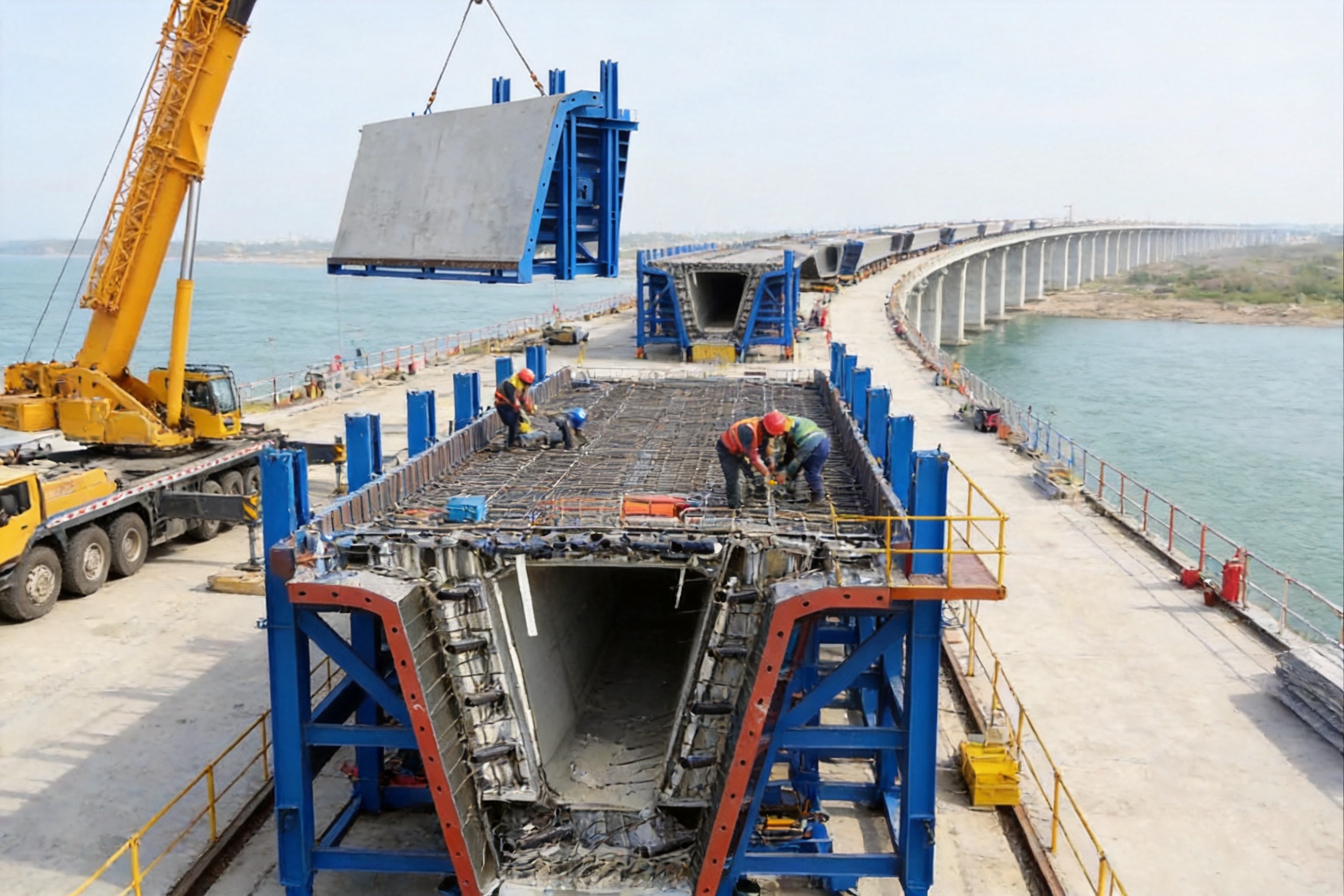
Box girder bridges are widely used in high-speed railway systems, expressways, urban viaducts, interchanges, and cross-sea transportation infrastructure. Their hollow structural design provides an efficient balance between strength, stiffness, self-weight, and material consumption. However, the quality, speed, and safety of box girder construction depend heavily on the performance of the formwork used during concrete casting.
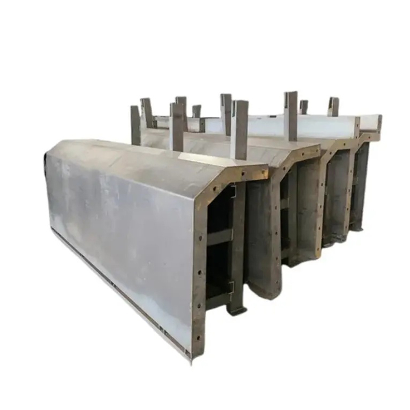
Box Girder Formwork is a specialized steel forming system developed for the demanding requirements of modern bridge construction. It is designed to support large-scale prefabrication yard production as well as on-site cast-in-place operations. The system combines high-strength steel fabrication, precision machining, modular construction, hydraulic adjustment, leak-proof sealing, and efficient demolding. These features help contractors produce box girders with stable dimensions, smooth surfaces, and consistent quality over repeated casting cycles.
Manufactured from Q235B and Q345 structural steel, the formwork is engineered to resist the considerable pressure generated during concrete pouring and vibration. Reinforcing components, accurately fabricated panels, adjustable connections, and carefully processed interfaces work together to reduce deformation and grout leakage. As a result, the completed concrete girder can often be used without extensive secondary plastering or surface repair.
The product is manufactured by Nantong Hyson Road And Bridge Formwork Co., Ltd., a specialized supplier of bridge formwork, steel structures, scaffolding, and heavy metal fabrication. With more than 15 years of experience in bridge formwork manufacturing, the company has developed equipment and production methods suitable for major infrastructure projects, including benchmark bridge applications such as the Sutong Bridge.
This article examines the structure, technical advantages, manufacturing process, applications, customization capabilities, and purchasing considerations associated with advanced box girder formwork.
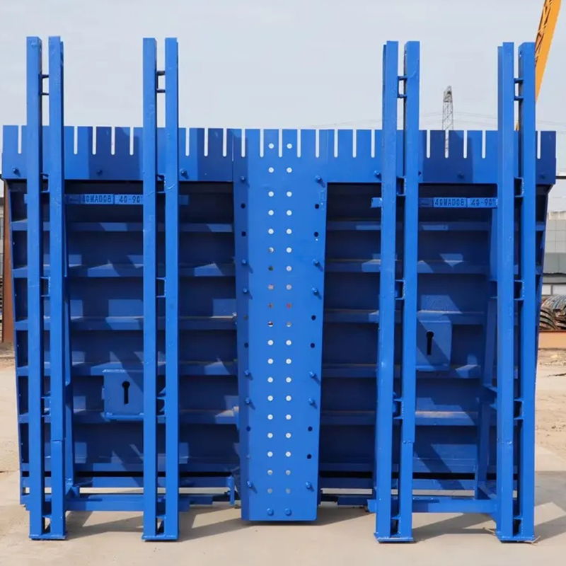
Box Girder Formwork
1. The Role of Formwork in Box Girder Construction
Formwork provides the temporary geometry that defines the shape of fresh concrete until the concrete develops sufficient strength to support itself. In box girder construction, the formwork must shape the external profile, internal cavity, deck, webs, diaphragms, and other structural features while maintaining the specified tolerances throughout pouring and curing.
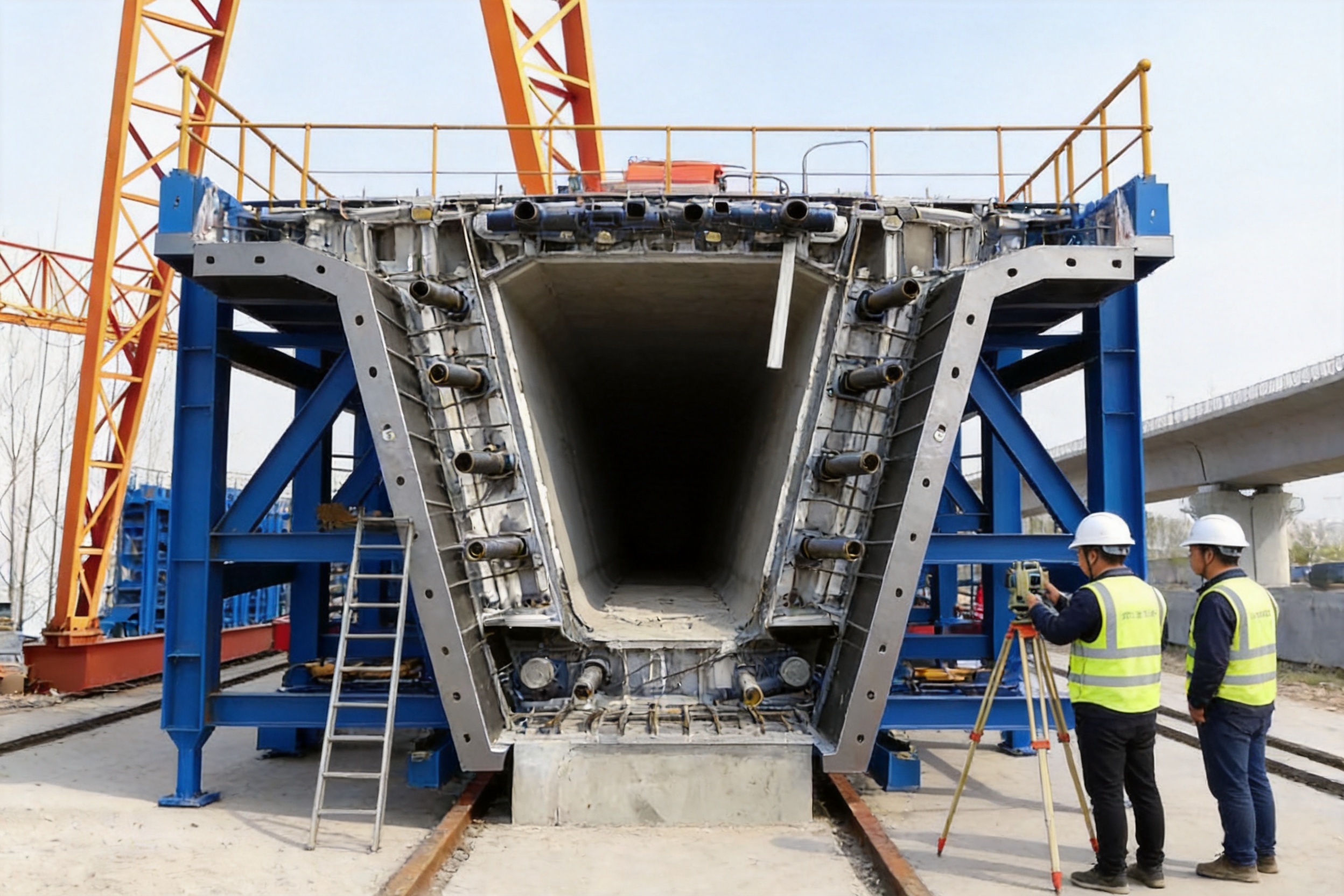
Unlike simple beam molds, box girder formwork normally includes several coordinated assemblies. These may include an external mold, internal mold, end mold, side panels, bottom support, working platforms, access components, hydraulic cylinders, adjustment devices, and connection hardware. Each assembly must work in a controlled sequence so that reinforcement placement, concrete pouring, curing, demolding, and formwork turnover can proceed efficiently.
Fresh concrete creates substantial lateral and vertical pressure. The pressure can be increased by high pouring speed, concrete fluidity, vibration, temperature, and the height of the formwork. If the mold lacks sufficient stiffness, the panels may bulge, joints may open, or the final girder may exceed the required dimensional tolerance. A deformed mold can also create uneven concrete thickness, misaligned webs, irregular edges, and problems during girder installation.
Leakage is another important concern. Even small gaps between panels may allow cement paste to escape. This can result in honeycombing, exposed aggregate, weak edges, dirty surfaces, and time-consuming repair work. For high-speed railway and major highway projects, repeated surface defects can increase labor costs and delay production schedules.
Advanced box girder formwork addresses these challenges through an integrated approach. Structural steel strength, panel accuracy, sealing design, hydraulic operation, modular connections, and surface treatment are considered together rather than as separate features.
2. Product Structure and Main Components
2.1 External Formwork
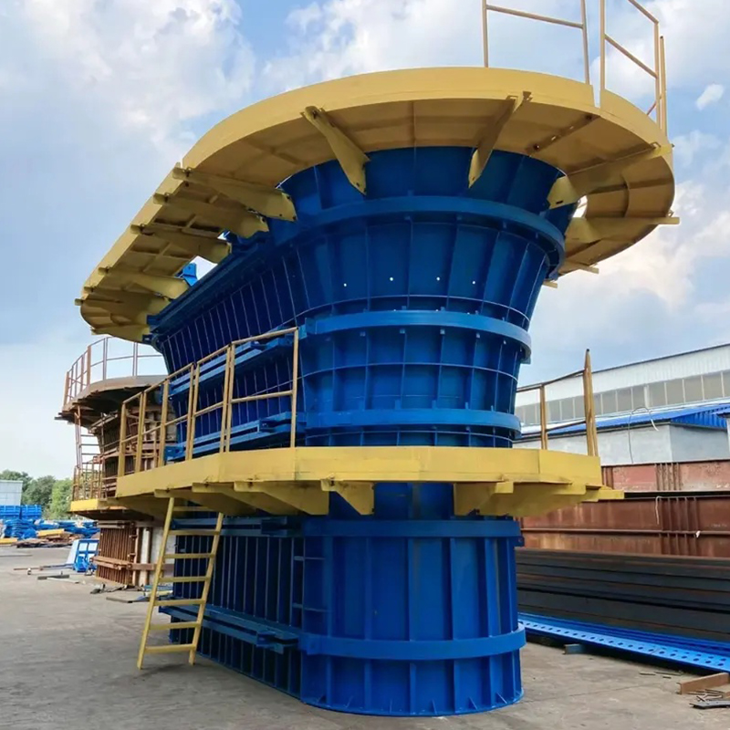
The external formwork defines the outside profile of the box girder. It generally consists of side panels, bottom panels, support frames, longitudinal stiffeners, transverse reinforcement, and adjustment mechanisms. The external mold must remain stable under concrete pressure while also allowing convenient access for reinforcement installation, inspection, vibration, and finishing operations.
Q235B or Q345 steel can be selected according to structural requirements, project conditions, and customer specifications. Q345 is commonly considered when higher strength or increased load resistance is required, while Q235B can be used for suitable structural and secondary components. The final selection depends on the engineering design, load calculations, applicable standards, and fabrication plan.
2.2 Internal Formwork
The internal formwork creates the hollow cavity inside the box girder. It must be dimensionally accurate because the internal width, height, corner radius, and web spacing influence the structural performance and installation compatibility of the finished girder.
The internal mold can be designed with adjustable or retractable sections. A hydraulically operated internal mold can reduce the time required to release the mold from the concrete. Instead of depending entirely on manual dismantling, operators can use controlled hydraulic movement to contract, reposition, and expand the internal assembly.
This arrangement is especially valuable in prefabrication yards where a large number of similar girders must be produced. Faster internal mold operation allows the production line to achieve more efficient turnover while reducing the need for repeated crane operations.
2.3 End Formwork
End formwork controls the end geometry of the box girder and provides a defined interface for subsequent installation, segment connection, or bridge assembly. It may include openings, embedded component positions, connection features, and special profiles required by the project design.
Accurate end formwork is essential for segmental construction. If the end profile is inconsistent, adjacent segments may not align properly. Precision machining and controlled assembly help maintain repeatable end dimensions across multiple casting cycles.
2.4 Hydraulic Adjustment System
The optional hydraulic system supports efficient mold opening, closing, contraction, expansion, and repositioning. Hydraulic cylinders can be integrated into the internal mold or other adjustable sections, depending on the project arrangement.
The system is designed to simplify demolding and reduce manual labor. It can also reduce crane utilization, which is important in busy prefabrication yards where lifting equipment may otherwise become a production bottleneck. Controlled hydraulic movement helps protect the concrete edges and reduces the risk of damage caused by forced or uneven mold removal.
2.5 Connection and Alignment Components
Standardized connection components, quick-locking pins, alignment guide rails, adjustable panels, and positioning devices make the formwork easier to assemble and modify. These parts help workers maintain the intended relationship between panels during installation.
Guide rails and alignment devices are particularly useful when a mold must be repeatedly assembled, adjusted, or transferred between production positions. They reduce dependence on improvised alignment methods and help create a more repeatable working process.
2.6 Working Platforms and Access Features
Bridge formwork systems may be equipped with working platforms, ladders, guardrails, access walkways, and maintenance areas according to project requirements. These features allow operators to inspect joints, install reinforcement, monitor concrete placement, and conduct cleaning or maintenance work more safely.
Platform and access arrangements must be coordinated with the casting sequence. A well-planned system allows workers to reach critical areas without interfering with hydraulic components or creating unnecessary obstacles around the mold.
3. Technical Advantages Over Conventional Formwork
3.1 Higher Resistance to Deformation
The first major advantage is structural stability. The formwork uses high-strength steel components together with reinforcing bars, stiffeners, and support frames. This arrangement enables the mold to resist the large forces generated by fresh concrete and vibration.
Compared with lightweight or insufficiently reinforced formwork, a properly engineered steel system is less likely to expand, twist, or develop permanent deformation during repeated use. Stable panels help preserve the designed girder geometry and reduce the risk of dimensional deviations.
Deformation resistance is also important for worker safety. A mold that moves unexpectedly under load can create dangerous gaps, unstable working conditions, or sudden stress on connection components. A rigid and properly supported structure provides a more controlled working environment.
3.2 Improved Dimensional Accuracy
Box girders used in high-speed railways and modern viaducts often require close control of dimensions. The girder must match design drawings, reinforcement arrangements, bearing systems, erection equipment, and adjacent structural elements.
Precision machining, controlled steel fabrication, accurate panel assembly, and adjustable positioning components help maintain the required dimensions. When the formwork is correctly installed and maintained, it can produce repeatable girder geometry over many production cycles.
Dimensional accuracy also reduces downstream adjustment. A girder with consistent width, height, web position, and end profile is easier to inspect, transport, install, and connect.
3.3 Reduced Grout Leakage
Leak-proof performance is a key quality feature. The product uses precision-machined interfaces and proprietary sealing methods to reduce the possibility of cement paste escaping through panel joints.
Effective sealing helps prevent honeycombing, surface cavities, exposed aggregate, and dirty edges. It also reduces the need for patching, grinding, or secondary plastering after demolding. This contributes to a cleaner appearance and lowers the amount of repair labor required for each girder.
Leakage prevention depends not only on the initial design but also on correct assembly, joint cleaning, bolt or pin tightening, sealing material condition, and regular maintenance. The formwork is therefore designed to make critical interfaces accessible for inspection and service.
3.4 Faster Demolding and Repositioning
Traditional formwork may require extensive manual dismantling before the internal mold can be removed. This consumes labor and can slow down the production cycle. The hydraulic adjustment option allows the internal mold to be contracted and released more efficiently.
Faster demolding helps reduce the time between casting operations. In a large prefabrication yard, even a small reduction in cycle time can produce significant benefits over hundreds of girders. Reduced crane dependence may also improve yard logistics and allow lifting equipment to serve other operations.
3.5 Modular Adaptability
Different projects may require different beam lengths, cross-sections, curves, widths, heights, or end arrangements. A fixed mold designed for only one geometry can become difficult to reuse when project conditions change.
The modular design of this formwork uses standardized connection components and adjustable panels. Depending on the engineering configuration, the system can be adapted to different beam lengths, variable cross-sections, curved structures, and other non-standard requirements.
This flexibility can improve equipment utilization. Contractors, precast yards, and rental companies may be able to use the same basic system across multiple projects after replacing or adjusting selected components instead of purchasing a completely new mold.
3.6 Long Service Life and High Turnover
The formwork is designed for repeated use. With appropriate cleaning, lubrication, alignment checks, sealing replacement, and surface protection, the system may achieve approximately 200 to 500 reuse cycles, depending on operating conditions and maintenance quality.
High turnover is particularly important for mass production. The cost of formwork is distributed across a larger number of girders, reducing the average tooling cost per unit. Durable construction also helps avoid frequent replacement and unexpected production interruptions.
The actual service life depends on concrete type, release-agent selection, handling practices, storage conditions, impact damage, corrosion exposure, maintenance procedures, and the number of modifications made during the project.
4. Manufacturing Process and Quality Control
The performance of box girder formwork depends on the entire manufacturing process. Strong raw material alone is not sufficient. The steel must be correctly cut, formed, welded, assembled, inspected, protected, and documented.
4.1 Engineering Review and Custom Design
Production begins with review of the customer’s structural drawings, girder dimensions, casting method, production sequence, site limitations, lifting arrangements, and applicable standards. Engineers assess whether the system will be used in a prefabrication yard, on a casting platform, or in a more complex site environment.
The design review considers external dimensions, internal cavity geometry, concrete pressure, support locations, hydraulic stroke, demolding direction, access requirements, lifting points, adjustment ranges, and maintenance access. Special features such as diaphragms, openings, embedded plates, inspection windows, and curved sections are incorporated into the design where required.
A detailed design stage helps prevent fabrication conflicts. It also allows the manufacturer to identify which components should be standardized and which parts require project-specific customization.
4.2 CNC Steel Plate Cutting
Advanced laser cutting and other CNC processing technologies are used to produce steel plates and components with controlled dimensions. Automated cutting reduces manual layout errors and creates consistent edges for subsequent forming and welding.
Laser cutting is particularly useful for connection plates, stiffeners, brackets, access components, bolt patterns, and complex profiles. Accurate cutting supports better assembly and reduces the need for excessive grinding or correction.
For heavy steel fabrication, plate thickness, heat input, cutting speed, edge condition, and material traceability must be controlled. Components can be identified and organized according to assembly drawings to improve production efficiency.
4.3 Bending, Forming, and Structural Assembly
After cutting, selected plates are bent or formed to create curved sections, side panels, internal profiles, and other geometric features. Bending accuracy is important because excessive deviation can create stress during assembly or change the intended concrete profile.
Structural frames, ribs, stiffeners, and support members are then assembled according to approved drawings. Fixtures and temporary positioning tools help maintain alignment during tack welding and final welding.
4.4 Certified Welding Processes
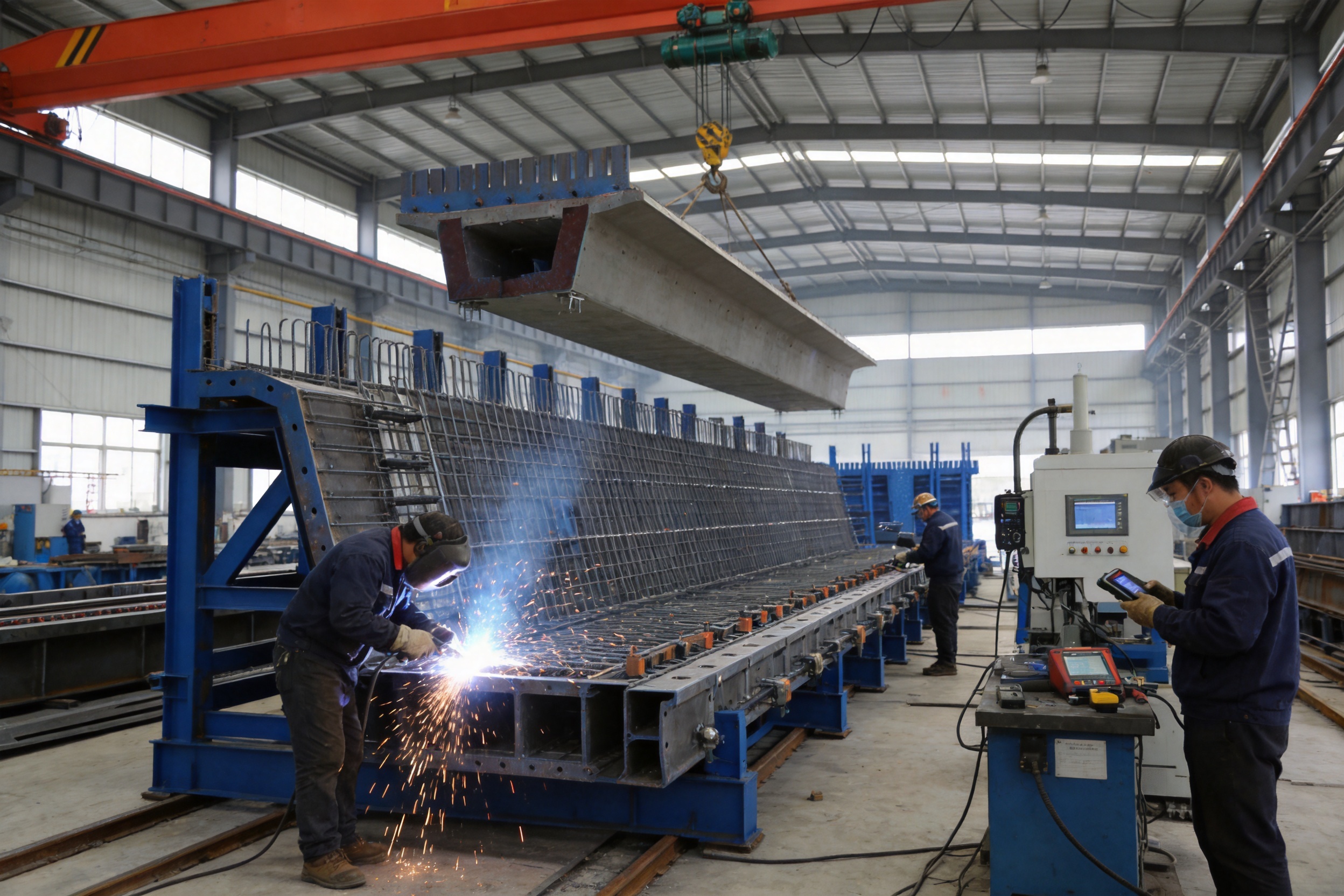
Welding is one of the most important stages in heavy steel formwork manufacturing. The company applies AWS and EN welding craftsmanship, supported by qualified personnel, controlled procedures, and inspection practices.
Welded joints must have sufficient strength, continuity, and dimensional stability. Welding sequence is planned to reduce distortion. Where necessary, components are welded symmetrically or in a controlled sequence so that heat input does not pull panels out of alignment.
Quality control may include visual inspection, dimensional inspection, weld profile checks, and additional non-destructive testing according to project requirements. Welding records, material certificates, and inspection documentation can support traceability for major infrastructure projects.
4.5 Precision Machining and Fitting
Machining is used for connection surfaces, guide components, hydraulic mounting areas, pin holes, bolt interfaces, and other parts where accurate fit is necessary. Proper machining improves assembly consistency and helps minimize gaps between connected components.
Precision fitting is also important for moving parts. Hydraulic mold sections must operate without excessive friction, interference, or uneven loading. Guide rails and locking devices must be positioned so that the mold can be repeatedly opened and closed without damaging the structure.
4.6 Trial Assembly and Dimensional Inspection
Before delivery, the formwork can be trial-assembled in the workshop. This allows the manufacturer to verify panel alignment, connection fit, hydraulic movement, access arrangements, and overall dimensions.
Trial assembly is especially valuable for large and complex systems. It can identify interference between components before the equipment reaches the construction site, where corrections may be more expensive and time-consuming.
Inspection may include checking length, width, height, diagonals, panel flatness, connection locations, hydraulic stroke, locking positions, and working platform dimensions. Any deviation is reviewed and corrected before shipment.
4.7 Surface Treatment and Protection
Steel surfaces are cleaned and treated to improve corrosion resistance and extend service life. Protective coatings can be selected according to the working environment, including ordinary inland construction, humid coastal conditions, or marine bridge projects.
Surface protection is important because concrete, water, release agents, salt, and outdoor storage can accelerate corrosion. Proper coating, drainage, storage, and maintenance help preserve the formwork during long construction schedules.
5. Comparison with Alternative Forming Solutions
| Evaluation Factor | Advanced Box Girder Steel Formwork | Basic Fixed Steel Mold | Lightweight or Improvised Formwork |
|---|---|---|---|
| Structural strength | High-strength steel, reinforcing members, and designed support frames | Generally stable but may have limited adjustment and reinforcement | More sensitive to concrete pressure and handling loads |
| Dimensional consistency | Precision fabrication, guide rails, adjustable panels, and trial assembly | Good for one fixed geometry when carefully maintained | May vary due to manual adjustment and component wear |
| Demolding efficiency | Hydraulic contraction and controlled repositioning available | Often requires greater manual dismantling | May require extensive labor and temporary support |
| Adaptability | Modular components can support different lengths and sections | Usually optimized for a limited configuration | Can be modified but may lose accuracy and stability |
| Leakage control | Precision interfaces and sealing design reduce grout loss | Depends heavily on manual fitting and maintenance | Joint leakage risk can be higher |
| Production efficiency | Suitable for repeated casting and high-turnover prefabrication | Suitable for stable, repetitive production | Usually less suitable for large-scale standardized output |
| Long-term value | Designed for approximately 200–500 cycles with proper maintenance | Service life depends on design and use conditions | May require more frequent repair or replacement |
This comparison is not intended to suggest that one formwork type is suitable for every project. Basic fixed molds may be economical for a small number of identical girders, while lightweight systems may be useful for temporary or low-load applications. However, large infrastructure projects generally benefit from a system that combines strength, accuracy, fast turnover, and adaptability.
6. Applications in Major Infrastructure Projects
6.1 High-Speed Railway Bridges
High-speed railway bridges require strict control of girder dimensions, surface quality, alignment, and production consistency. Box girders are often manufactured in large quantities in dedicated prefabrication yards. The formwork must therefore support a repeatable casting cycle and stable quality across many units.
The modular steel system is suitable for both single-track and double-track box girders, subject to project design. Hydraulic internal molds can improve cycle times, while precision sealing helps reduce surface repair. Consistent girder geometry also supports transportation and erection operations.
6.2 Highway Viaducts and Interchanges
Highway projects frequently include ramps, curved alignments, variable cross-sections, continuous beams, and non-standard spans. A modular formwork system can be adjusted to accommodate different project sections more effectively than a completely fixed mold.
For cast-in-place viaduct work, formwork must also fit within site constraints. Access, crane availability, foundation conditions, and construction sequencing can vary significantly from one location to another. Adjustable components and hydraulic operation help the contractor respond to these conditions.
6.3 Precast Beam Yards
Precast beam yards depend on production efficiency. Each casting position must be prepared, poured, cured, released, cleaned, and prepared again within a planned cycle. Delays in one stage can affect the entire yard.
Box girder formwork with quick-locking connections, hydraulic demolding, and high reuse capacity is well suited to this environment. The equipment can support segmental box girder production and other high-precision precast applications when designed to match the required geometry.
6.4 Sea-Crossing Bridges
Marine bridge projects expose equipment to humidity, salt spray, wind, and difficult logistics. Corrosion-resistant surface treatment and robust steel construction are therefore important considerations.
Formwork for sea-crossing bridges may require enhanced coating systems, sealed hydraulic components, corrosion-resistant hardware, and additional inspection routines. The product can be configured for demanding marine construction environments when the protection system and maintenance plan are selected appropriately.
6.5 Urban Elevated Roads
Urban viaduct projects often operate within restricted spaces and near existing traffic, buildings, utilities, and public facilities. The formwork must be easy to position, adjust, inspect, and remove without creating unnecessary disruption.
Modular construction allows selected components to be adapted to the available work area. Hydraulic operation can reduce the number of heavy lifting actions, while integrated access features support safer inspection and maintenance in confined environments.
7. Manufacturing Strengths and Integrated Capabilities
The manufacturer’s ability to produce box girder formwork is supported by broader heavy-industry capabilities. The company specializes in custom steel formwork, ringlock scaffolding, heavy-duty steel structures, and OEM metal fabrication.
Advanced laser cutting equipment allows the production of high-precision components for large and non-standard assemblies. Standardized production lines help improve consistency across multiple orders, while automated processing reduces dependence on manual cutting and layout work.
The company also provides integrated bending, welding, and assembly services. This is valuable for customers seeking a single supplier for complete steel components rather than coordinating separate cutting, forming, and welding workshops.
AWS and EN welding practices support the manufacture of structural steel products for international customers. The company operates under ISO 9001 quality management principles and has 12 utility patents associated with its technical development. It also works with BS1139 and EN74-related requirements for relevant scaffolding and steel equipment products.
Experience serving major state-owned construction enterprises, including CCCC and CRCC-related projects, provides exposure to demanding procurement, fabrication, inspection, and delivery requirements. The company’s project experience includes the Sutong Yangtze River Bridge, Taizhou Bridge, and Sudan Thermal Power Plant.
These capabilities contribute to a practical advantage for buyers. Instead of purchasing a generic product and arranging extensive local modification, customers can request a formwork system designed around their drawings, production method, lifting capacity, and project conditions.
8. Customization Options
8.1 Geometry and Beam Dimensions
Formwork can be customized for different box girder lengths, widths, heights, web thicknesses, deck configurations, and internal cavities. The exact range depends on the structural design and the intended casting sequence.
Variable cross-sections can be addressed through adjustable panels or interchangeable modules. Curved sections may require special panel geometry, support arrangements, or controlled positioning devices.
8.2 Casting Method
The system can be designed for prefabrication yard production, segmental casting, on-site casting, or other project-specific methods. Each method affects the arrangement of supports, platforms, hydraulic components, lifting points, and access systems.
For a prefabrication yard, rapid repetition and easy mold turnover may be the primary objectives. For on-site construction, compact layout, adaptable support, and convenient relocation may be more important.
8.3 Hydraulic Configuration
Hydraulic operation can be configured according to the required mold movements. The number and location of cylinders, control valves, hoses, supports, and locking devices depend on mold size and operating sequence.
Customers may specify manual, semi-hydraulic, or more integrated hydraulic arrangements. A suitable control system should provide stable movement without sudden impact and should include inspection and maintenance access.
8.4 Surface Protection
Coating and corrosion protection can be selected according to the environment. Inland projects may use a standard industrial coating, while coastal and marine applications may require enhanced preparation and protective systems.
Customers should also clarify whether the mold will be stored outdoors, transported between locations, or exposed to high humidity. These factors influence the recommended surface treatment and maintenance plan.
8.5 Embedded Components and Special Openings
Box girders often contain drainage openings, anchor systems, lifting points, embedded plates, inspection features, and other project-specific details. The formwork can incorporate corresponding openings and positioning components where these are included in the approved drawings.
Accurate integration of these details reduces the need for field modification and helps maintain consistent positioning across repeated girders.
9. Installation and Operating Sequence
A typical installation sequence begins with checking the foundation or casting platform. The support base must have sufficient capacity and levelness to carry the formwork and fresh concrete loads. Survey points are established to control the position and elevation of the mold.
External panels and support frames are then positioned and connected. Alignment guide rails, quick-locking pins, bolts, and adjustment devices are checked before the internal mold is installed. Hydraulic components are connected and tested according to the operating instructions.
After the mold is aligned, reinforcement cages, embedded parts, ducts, and other components are installed. Operators inspect clearances between reinforcement and formwork. Sealing joints are cleaned, and release agent is applied evenly to the appropriate surfaces.
Before concrete pouring, the contractor checks panel connections, access platforms, guardrails, hydraulic locks, formwork dimensions, embedded items, and cleanliness. Concrete is then placed according to the approved sequence to avoid excessive unbalanced pressure.
During pouring, workers monitor the formwork for movement, leakage, abnormal sound, hydraulic changes, and other signs of instability. Concrete vibration should be controlled to achieve proper compaction without causing excessive pressure or displacement.
After curing reaches the specified release condition, the internal mold is contracted using the hydraulic system or designated manual procedure. External components are released in the correct sequence, and the girder is inspected after demolding.
The mold is then cleaned immediately. Concrete residue is removed from panel faces, joints, guide rails, pins, and hydraulic components. Damaged seals are replaced, moving parts are lubricated, and dimensional checks are performed before the next cycle.
10. Maintenance and Service-Life Management
Maintenance has a direct effect on formwork performance and reuse cycles. A durable mold can still suffer premature damage if concrete buildup, impact, corrosion, or poor storage is ignored.
After each casting cycle, workers should remove residual concrete without damaging the steel surface. Sharp tools or uncontrolled impact can create dents and scratches that later affect the concrete finish. Suitable cleaning methods should be selected according to the coating and panel material.
Connection pins, bolts, guide rails, hinges, hydraulic cylinder mounts, and locking devices should be inspected regularly. Loose or damaged components should be corrected before the next pour. Hydraulic hoses and fittings should be checked for leakage, abrasion, and mechanical damage.
Panel flatness and alignment should be reviewed at planned intervals. Repeated loading, lifting, and movement can gradually alter the position of components. Early correction is generally more economical than allowing dimensional errors to accumulate across multiple girders.
When the formwork is not in use, it should be stored on stable supports with suitable drainage and protection. Openings should be protected from water accumulation, and hydraulic parts should be stored according to the manufacturer’s instructions.
Maintenance records can include cycle count, repair history, seal replacement, coating condition, dimensional inspections, and hydraulic service. These records help the contractor plan preventive maintenance and estimate the remaining service life of the equipment.
11. Safety Considerations
Box girder formwork is large and heavy equipment. Safe operation requires trained personnel, approved lifting plans, stable foundations, and clear communication during assembly and demolding.
Workers should not enter restricted areas during hydraulic movement or lifting operations. Locking devices must be fully engaged before concrete pouring. Temporary supports must not be removed until the responsible engineer or supervisor confirms that the system is stable.
Working platforms, ladders, guardrails, and access routes should be inspected before use. Operators should have adequate lighting and unobstructed visibility around the mold. Hydraulic systems should include suitable control procedures to prevent unexpected movement.
Concrete pouring should follow an approved sequence. Excessive one-sided filling may create unbalanced pressure and increase the risk of mold movement. The pouring rate and vibration process should be coordinated with the formwork design.
Safety requirements may differ according to local regulations and project specifications. The contractor remains responsible for site risk assessment, worker training, equipment inspection, and compliance with applicable laws.
12. Economic Value for Contractors and Precast Producers
The economic value of formwork is determined by more than its initial purchase price. Productivity, repair requirements, labor demand, crane usage, surface quality, service life, and adaptability all influence the total cost of ownership.
A hydraulic demolding system can reduce labor intensity and shorten the release process. Lower crane dependence may improve the utilization of yard equipment. Faster turnover can increase the number of girders produced by a casting position within a given period.
Leak-proof panel joints reduce repair work. When concrete surfaces are smooth and free from major honeycombing, the contractor can reduce patching materials, labor hours, inspection delays, and corrective operations.
Modular adaptability can also protect the investment. If a project includes multiple girder types or if the equipment is later transferred to another project, adjustable modules may allow continued use instead of complete replacement.
The expected reuse range of approximately 200 to 500 cycles provides a basis for evaluating long-term value. The actual result depends on maintenance and site conditions, but a high-turnover system is generally more suitable for large production programs than a short-life temporary mold.
13. Selecting the Right Box Girder Formwork Supplier
Customers should begin by confirming whether the supplier has experience with the intended bridge type and casting method. Experience with high-speed railway, highway, marine, and prefabrication projects can indicate familiarity with different design and production challenges.
The supplier’s manufacturing capacity should also be reviewed. Important questions include whether it has CNC cutting equipment, heavy welding capability, large assembly space, dimensional inspection procedures, hydraulic testing facilities, and surface treatment resources.
Quality documentation is another important consideration. Buyers may request material certificates, welding qualifications, inspection records, design drawings, hydraulic component information, coating specifications, and trial assembly reports.
Customization support should be evaluated before placing an order. The supplier should be able to review the customer’s girder drawings, propose a mold configuration, clarify adjustment ranges, and identify any limitations related to transportation, installation, or site operation.
After-sales support is also relevant. Technical guidance for assembly, commissioning, maintenance, spare parts, sealing components, and hydraulic troubleshooting can reduce start-up delays and improve long-term performance.
14. Why Integrated Heavy Steel Fabrication Matters
Box girder formwork combines structural steel fabrication, precision machining, hydraulic integration, welding, coating, and site-oriented engineering. A supplier with only basic steel cutting capability may not be able to control the complete production chain.
Integrated manufacturing reduces communication gaps between different subcontractors. Design changes can be coordinated more efficiently, and the supplier can take responsibility for the relationship between plates, frames, hydraulic devices, and connection components.
It also supports the production of related equipment. Customers working on major infrastructure projects may require tunnel trolleys, steel supports, scaffolding, industrial frames, bridge components, or other heavy steel assemblies. A manufacturer with broad capabilities can provide more consistent fabrication standards across the project.
For international buyers, integrated OEM production can simplify procurement. The customer provides drawings, specifications, standards, and project requirements, while the manufacturer manages cutting, forming, welding, assembly, inspection, coating, and shipment preparation.
15. Frequently Asked Questions
Q1: What is box girder formwork used for?
Box girder formwork is used to shape concrete box girders for high-speed railways, highways, viaducts, interchanges, precast beam yards, and sea-crossing bridges. It can be configured for prefabrication or on-site casting.
Q2: Which steel grades are used?
The main structural materials are Q235B and Q345 steel. The appropriate grade depends on the structural design, load requirements, component function, applicable standards, and customer specifications.
Q3: Can the formwork be customized?
Yes. The system can be customized for beam length, cross-section, internal cavity, curve, variable geometry, casting method, hydraulic arrangement, access platforms, embedded components, and surface protection requirements.
Q4: Does the product include a hydraulic system?
A hydraulic adjustment system is available as an optional or project-specific configuration. It can support internal mold contraction, demolding, repositioning, and expansion, reducing manual work and crane usage.
Q5: How many times can the formwork be reused?
With proper cleaning, alignment checks, lubrication, sealing maintenance, and surface protection, the formwork may be reused approximately 200 to 500 times. Actual service life depends on project conditions and operating practices.
Q6: Can it be used for marine bridge construction?
Yes. The formwork can be manufactured with corrosion-resistant design and suitable surface protection for humid or marine environments. The coating system and maintenance plan should be selected according to the site exposure.
Q7: How does the formwork reduce concrete surface defects?
Precision-machined interfaces and sealing technology reduce grout leakage. Stable panels also help maintain the designed geometry during pouring. Together, these features reduce the likelihood of honeycombing, uneven edges, and repair-intensive surface defects.
Q8: Is trial assembly performed before delivery?
Trial assembly and dimensional inspection can be performed to verify component fit, panel alignment, connection positions, hydraulic movement, and overall configuration before shipment.
Q9: What information is needed for a quotation?
Useful information includes girder drawings, external and internal dimensions, beam length, cross-section type, casting method, required production quantity, hydraulic preferences, applicable standards, site conditions, and delivery requirements.
Q10: What manufacturing capabilities support the product?
The manufacturer provides CNC laser cutting, bending, heavy steel assembly, AWS and EN welding practices, precision machining, surface treatment, hydraulic integration, inspection, and OEM fabrication services.
Q11: Can the formwork be used for both single-track and double-track railway girders?
It can be designed for single-track or double-track box girder applications when the dimensions and structural requirements are confirmed. The final configuration must be developed from the approved project drawings.
Q12: Does the supplier provide technical support?
Technical support may include design clarification, manufacturing documentation, installation guidance, commissioning assistance, maintenance recommendations, and spare component coordination, depending on the contract scope.
16. Conclusion
Box Girder Formwork is a critical production tool for modern bridge construction. Its performance directly influences girder geometry, concrete surface quality, production speed, labor requirements, and long-term project cost.
The system described in this article combines Q235B or Q345 steel, reinforced structural design, precision machining, hydraulic adjustment, modular connections, sealing technology, and protective surface treatment. These features provide important advantages over basic fixed molds and improvised forming systems, particularly when a project requires high repeatability, rapid turnover, and adaptable geometry.
Its applications include high-speed railway bridges, highway viaducts, interchanges, precast beam yards, urban elevated roads, and marine infrastructure. With suitable customization, it can accommodate different beam lengths, cross-sections, curves, casting methods, and environmental conditions.
The manufacturing strength behind the product is equally important. CNC laser cutting, controlled bending, certified welding practices, precision assembly, trial fitting, hydraulic testing, and quality management help create a reliable forming system for demanding infrastructure projects.
For contractors and precast producers, the best value comes from evaluating the complete service life of the equipment rather than focusing only on the purchase price. A durable, modular, hydraulic, and accurately manufactured box girder formwork system can reduce labor, improve casting efficiency, limit surface repair, and support hundreds of production cycles when properly maintained.
References
1. American Welding Society. Structural Welding Code—Steel, AWS D1.1/D1.1M.
2. European Committee for Standardization. EN 1090, Execution of Steel Structures and Aluminium Structures.
3. European Committee for Standardization. EN 74, Couplers, Spigot Pins and Baseplates for Use in Falsework and Scaffolds.
4. British Standards Institution. BS 1139, Metal Scaffolding Materials.
5. International Organization for Standardization. ISO 9001, Quality Management Systems—Requirements.
6. American Concrete Institute. ACI 347, Guide to Formwork for Concrete.
7. Federal Highway Administration. Bridge Construction and Inspection Guidance.
8. Relevant project drawings, structural design specifications, concrete casting procedures, and manufacturer technical documentation.
Product: Box Girder Formwork



- Location
- Group 3, Fangzhuang Village, Rucheng Subdistrict, Rugao City, Nantong, Jiangsu, China
- Follow us
- Phone
- +86-13646196162
- info@hysonindustry.com
